
Lifting loading platform

a technology for lifting platforms and loading platforms, which is applied to vehicles with raised loading platforms, transportation items, applications, etc., can solve the problems of relative thick and bulky hydraulic hoses that have to be laid, and achieve the effect of simple, cost-effective, reliable linear drives, raising, lowering and/or pivoting the loading platform

Inactive Publication Date: 2010-02-25
MBB PALFINGER GMBH
View PDF18 Cites 7 Cited by
  • Summary
  • Abstract
  • Description
  • Claims
  • Application Information

AI Technical Summary

Benefits of technology

[0007]Taking this as the starting point, the object on which the invention is based is to provide a tail lift which has simple, cost-effective and nevertheless reliable linear drives for raising, lowering and / or pivoting the loading platform.
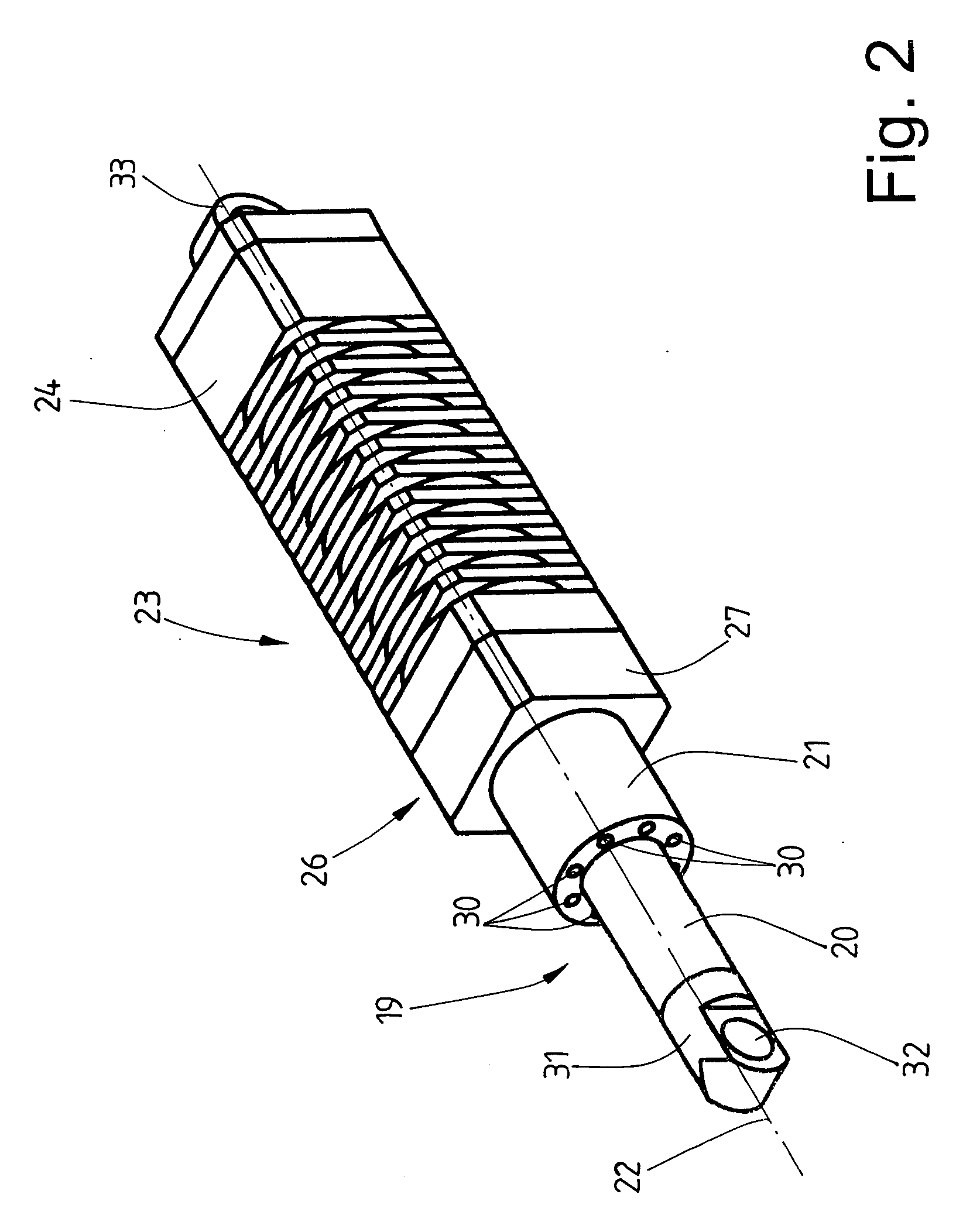
[0009]Preferably, the respective roller screw mechanism comprises an axially displaceable pushrod which is provided at least partially with a roller thread. The pushrod acts like the piston rod of a hydraulic cylinder, which means that the respective roller screw mechanism can have external dimensions comparable to those of a hydraulic cylinder, with the result that it is possible without significant modifications to provide the tail lift in the manner according to the invention with roller screw mechanisms.

Problems solved by technology

Although virtually all tail lifts have to date been provided with hydraulic cylinders for moving the loading platform, they have a major disadvantage which particularly concerns the fact that a hydraulic unit is required for operating the hydraulic cylinders and that relatively thick and bulky hydraulic hoses have to be laid from the hydraulic unit to the hydraulic cylinders.
If a leak occurs in a hydraulic hose as a result of damage, for example, then oil escapes, a situation which leads to serious contamination and is also critical from an environmental point of view.

Method used


Image

  • Lifting loading platform
  • Lifting loading platform
  • Lifting loading platform

Examples


Embodiment Construction

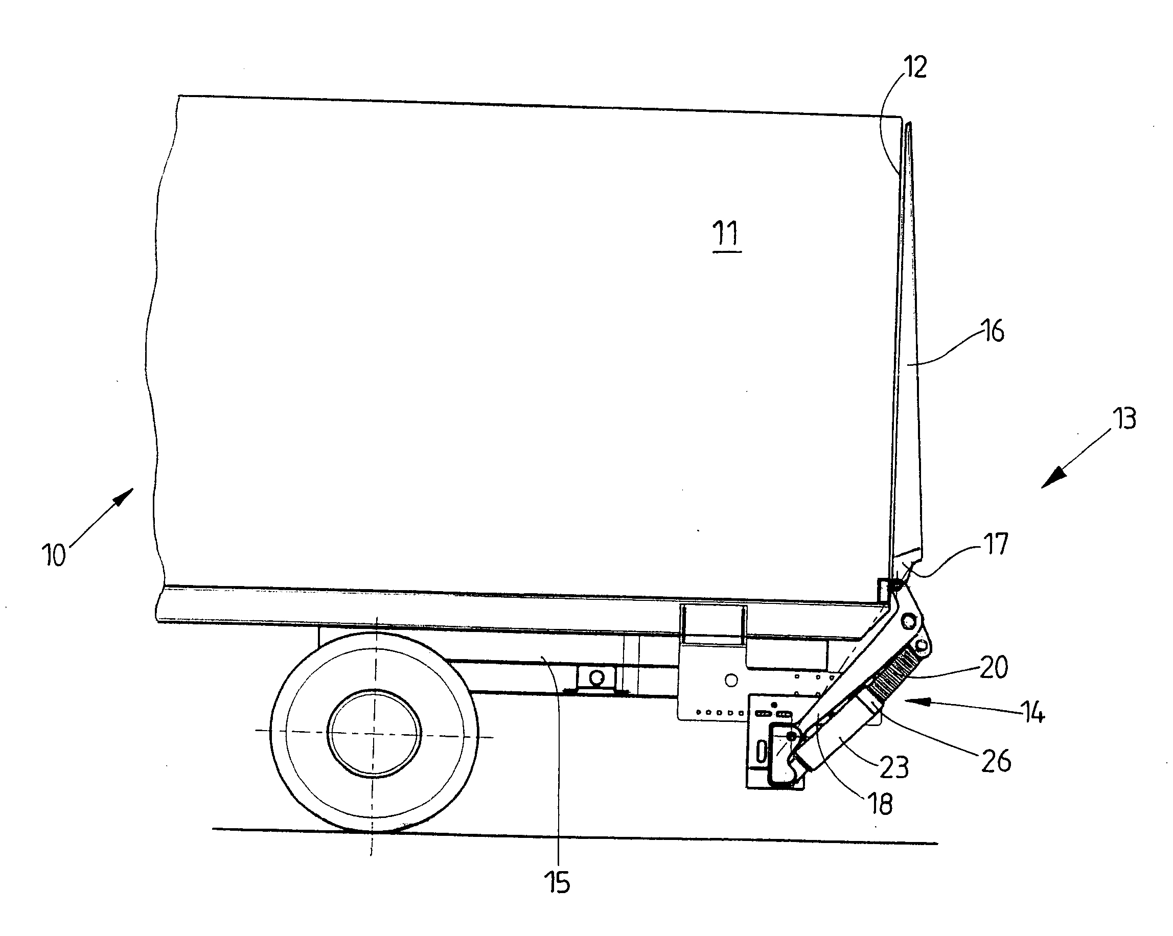
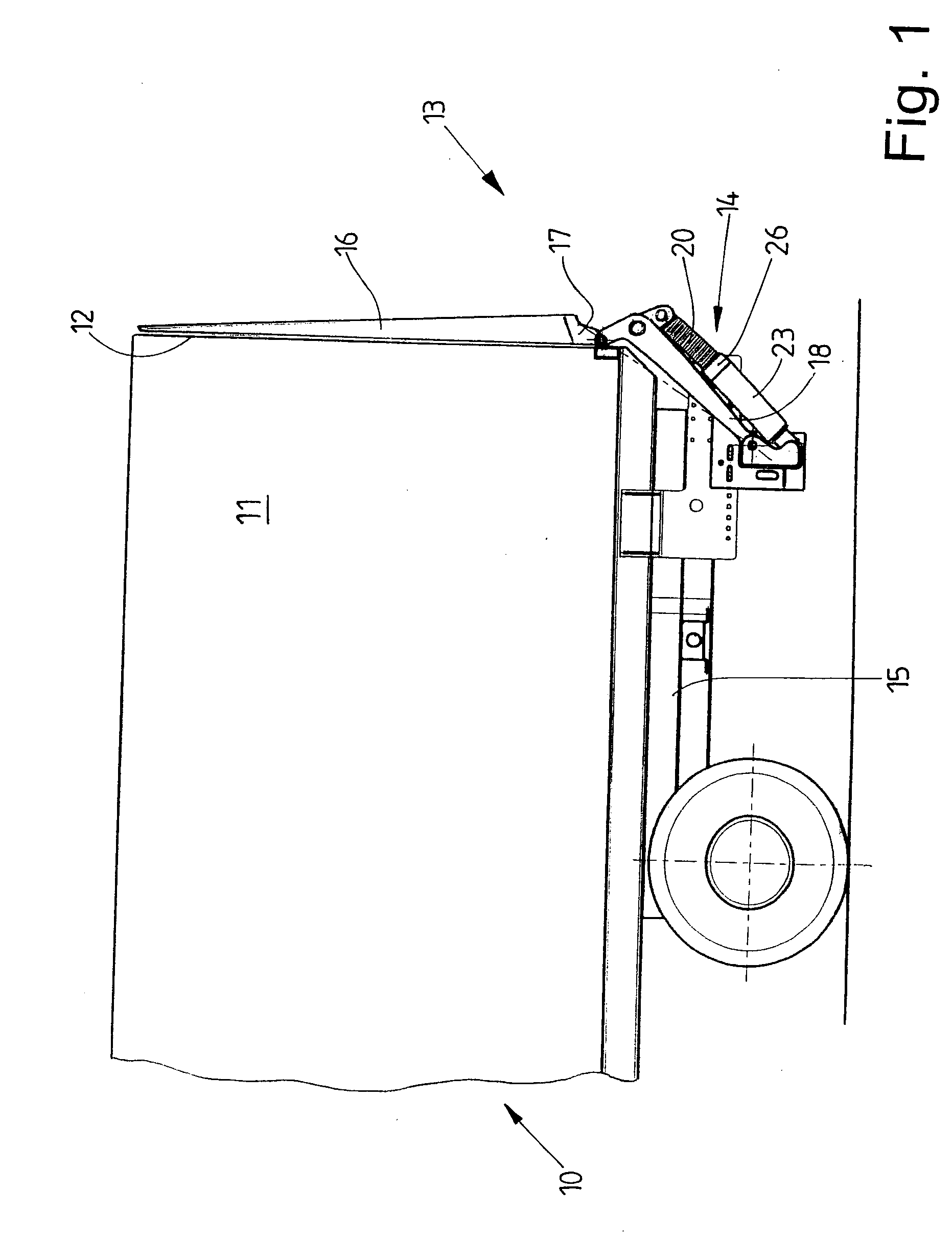
[0023]FIG. 1 shows a rear part of a vehicle, specifically a truck 10. The truck 10 has a body 11 which, in the exemplary embodiment shown, is a so-called box body. The body 11 has a rear side 12 which is at least partially open or which is to be opened. The rear side 12 can preferably be opened or closed by means of doors or the like.

[0024]The rear side 12 of the truck 10 is assigned the tail lift 13 according to the invention. The tail lift 13 has a lifting assembly 14 which is directly or indirectly fastened by means of a transversely directed support tube to a vehicle frame 15 of the truck 10, this frame being represented only by way of an outline in FIG. 1. The tail lift 13 also has a loading platform 16. The loading platform 16 is articulated on the lifting assembly 14 so as to be able to pivot on a lower (in relation to the representation in FIG. 1) transverse edge 17. The loading platform 16 can additionally be lowered and raised by the lifting assembly 14. FIG. 1 shows the c...


PUM


Abstract

Loading platforms (16) of tail lifts (13) are usually raised and lowered or pivoted by hydraulic cylinders. Hydraulic cylinders require a hydraulic unit. Furthermore, there is a risk of contamination through unsealed hydraulic lines. To raise, lower and / or pivot the loading platform (16) of the tail lift (13), the invention makes provision to use roller screw mechanisms (19) which are driven by hollow-shaft electric motors (23). As a result, hydraulic drives for the loading platform (16) are no longer required. Each roller screw mechanism (19) is driven by the hollow-shaft electric motor (23). The unit consisting of the roller screw mechanism (19) and the hollow-shaft electric motor (23) operates in principle like a known hydraulic cylinder and also has approximately the same dimensions, with the result that hydraulic cylinders can be replaced by roller screw mechanisms (19) with hollow-shaft electric motors (23) without significant modifications to the tail lift (13).

Description

STATEMENT OF RELATED APPLICATIONS[0001]This application is the U.S. National Phase Under Chapter II of the Patent Cooperation Treaty (PCT) of PCT International Application No. PCT / EP2007 / 007501 having an International Filing Date of 28 Aug. 2007, which claims priority on German Patent Application No. 10 2006 053 441.7 having a filing date 12 Sep. 2006.BACKGROUND OF THE INVENTION[0002]1. Technical Field[0003]The invention relates to a lifting loading platform, or tail lift, for attaching to a vehicle, with a loading platform and with a lifting assembly which comprises at least one linear drive and which is intended for raising, lowering and / or pivoting the loading platform.[0004]2. Prior Art[0005]Tail lifts are used to facilitate the operations of loading and unloading vehicles, particularly when heavy goods are involved. Such a tail lift has a loading platform which is preferably articulated on the rear side of a body of a vehicle such that it can be raised and lowered and usually p...

Claims


Application Information

Patent Timeline
Patent Type & Authority Applications(United States)
IPC IPC(8): B60P1/44B60P1/00
CPCF16H25/2252B60P1/4471
Inventor ZIMMERMANN, MARTIN
Owner MBB PALFINGER GMBH
Learn More