Multi-point sash lock system for casement window

a multi-point, casement window technology, applied in the direction of fastening devices, mechanical devices, carpet fasteners, etc., can solve the problems of difficult installation of the lock assembly on the window frame and sash, inability to fully lock the window sash, and the engagement structure may interfere with the window sash itself, so as to save assembly time, improve the accuracy of alignment of the guide, and the effect of greater length

Inactive Publication Date: 2007-05-03
TRUTH HARDWARE
View PDF26 Cites 16 Cited by
  • Summary
  • Abstract
  • Description
  • Claims
  • Application Information

AI Technical Summary

Benefits of technology

[0010] The present invention is an improved sash lock system for casement windows that addresses the needs of the industry. In an embodiment, the invention includes a tie bar assembly having a tie bar longitudinally slidable with a lock drive operable with a lever. The tie bar has a plurality of rollers for engaging keepers (known as biscuit keepers) spaced apart on the window sash. The tie bar is guided with a plurality of guides secured to the window frame. Each guide has a pair of spaced apart guide portions, each with a separate locating lip for engaging a pre located groove in the window frame. The spaced

Problems solved by technology

These known mechanisms, while being generally adequate for locking a window sash have not provided entirely satisfactory performance in some respects.
Installation of the lock assembly on the window frame and sash is difficult with some prior systems because it is necessary to carefully measure and accurately position the tie-bar at the correct distance from the locked position of the window sash.
If the tie bar is too close, the engaging structures may interfere with the window sash itself.
Although some prior art systems have addressed this problem by providing a locating lip on the tie-bar guide that engages in a pre-located groove in the window frame, these systems have not been entirely satisfactory in that the locating lip of the guide must fit snugly into the groove so as to avoid misalignment of the guide when it is secured to the window frame.
Such misalignment may cause binding of the tie bar in the guides.
Moreover, this operation consumes valuable time and effort in a mass production environment.
In some prior systems, this process must be done manually for each individual window, adding time and cost to assembly of the window.
Again, although some

Method used


Image

  • Multi-point sash lock system for casement window
  • Multi-point sash lock system for casement window
  • Multi-point sash lock system for casement window

Examples


Embodiment Construction

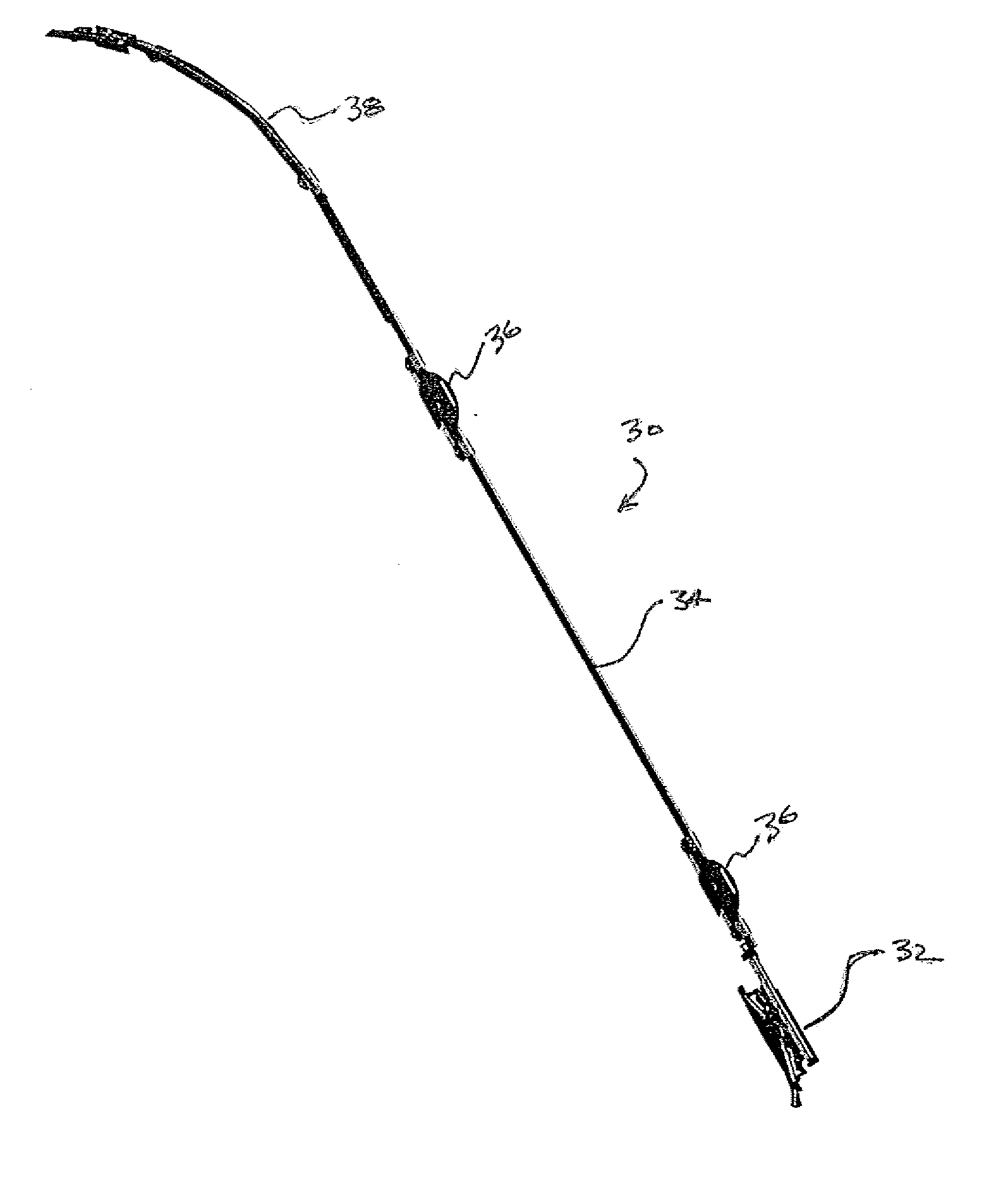
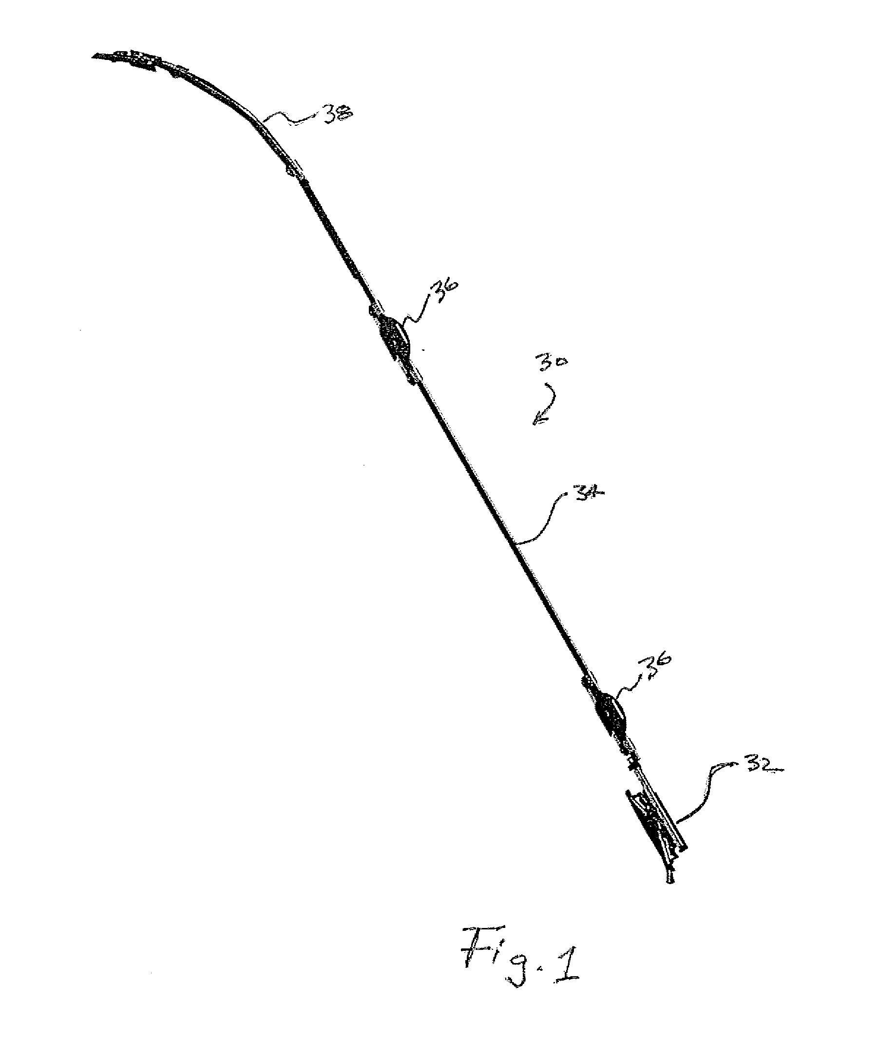
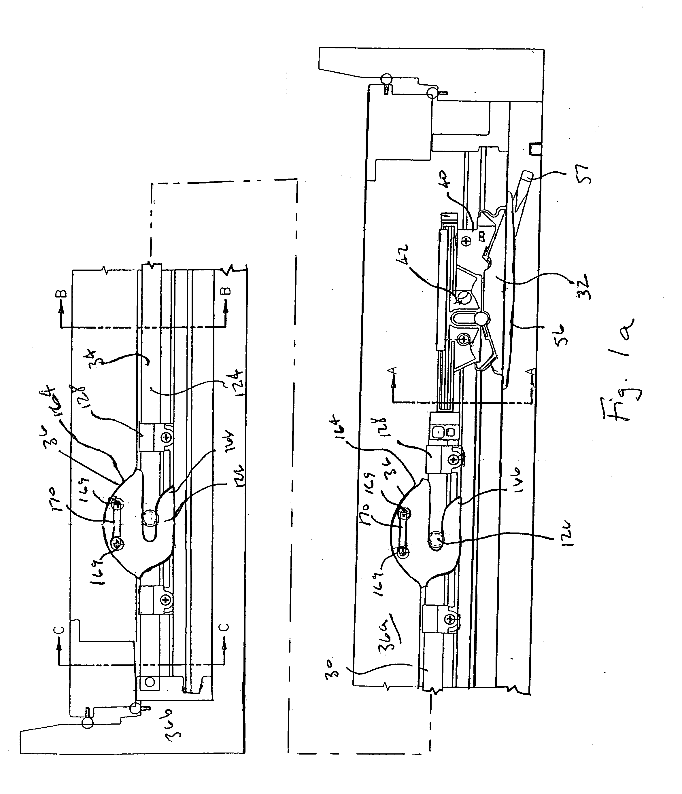
[0051] Referring now to FIGS. 1-1d, 29, and 29a, multi-point sash lock assembly 30 generally includes drive assembly 32, tie-bar assembly 34, and biscuit keepers 36. Multi-point lock assembly 30 is used to latch and lock an operable window sash 36a with a window frame 36b. Optional round top window tie bar assembly 38 (see FIGS. 22-28) may be coupled to tie-bar assembly 34 if desired for latching an operable sash round-top window (depicted in part in FIG. 28).

[0052] Drive assembly 32 (see FIGS. 1-12) generally includes base plate 40, slide 42, and lever 44. Lever 44 is pivotally attached to base plate 40 with rivet 46, which extends through aperture 48 in lever 44 and aperture 49 in base plate 40. As depicted in FIGS. 2 and 3, lever 44 has handle portion 50, hub portion 52, and inner actuating portion 54. When multi-point lock assembly 30 is mounted in a window sash (FIGS. 29 and 29a), handle portion 50 extends through a slot in the window frame to enable multi-point lock assembly ...


PUM


Abstract

A multi-point sash lock assembly being shiftable between a locked and an unlocked disposition includes a tie bar assembly including a tie bar guide, the tie bar guide having at least one guide end, the guide end being integrally, unitarily formed. A multi-point sash lock assembly for securing a rounded side of a window to a rounded window frame and a method of forming a multi-point sash lock assembly are further included.

Description

RELATED APPLICATION [0001] The present application claims the benefit of U.S. Provisional Application No. 60 / 677,429 filed May 2, 2005, which is incorporated herein in its entirety by reference.FIELD OF THE INVENTION [0002] The present invention relates to lock systems and more specifically to sash lock systems for casement windows. BACKGROUND OF THE INVENTION [0003] Multi-point sash lock systems for casement windows are known. Such known systems are disclosed in U.S. Pat. Nos. 4,803,808; 5,087,087; and 5,118,145, hereby fully incorporated herein by reference. These systems typically have a single operating control, usually a lever. The lever is typically linked to a tie-bar that has multiple engaging structures disposed at intervals along its length. Operation of the lever causes the tie-bar to move longitudinally. Keepers are attached to the window sash proximate the locations of each of the engaging structures so that as the tie-bar moves, the engaging structures are moved in and...

Claims


Application Information

Patent Timeline
IPC IPC(8): E05C1/02
CPCE05B17/0025E05B63/0056E05C9/1858E05C9/20E05C9/22Y10S292/20Y10T292/096Y10T292/432
Inventor VETTER, GREGORY J.
Owner TRUTH HARDWARE
Why Eureka
Try Eureka