RF power transmission, modulation, and amplification embodiments

a technology of rf power transmission and modulation, applied in the direction of modulation, gain control, amplifier modification to reduce non-linear distortion, etc., can solve the problem of linearity and power efficiency, linearity of power amplifiers, and less power efficiency, so as to achieve cost-saving effects

Inactive Publication Date: 2007-05-03
PARKER VISION INC
View PDF101 Cites 153 Cited by
  • Summary
  • Abstract
  • Description
  • Claims
  • Application Information

AI Technical Summary

Benefits of technology

[0018] Embodiments of the invention can be implemented with analog and / or digital controls. The invention can be implemented with analog components or with a combination of analog components and digital components. In the latter embodiment, digital signal processing can be implemented in an existing baseband processor for added cost savings.

Problems solved by technology

In power amplifiers, a complex tradeoff typically exists between linearity and power efficiency.
Unfortunately, the traditional tradeoff between linearity and efficiency in power amplifiers is such that the more linear a power amplifier is the less power efficient it is.
On the other hand, higher class amplifiers such as class B,C,D,E, etc, are more power efficient, but are considerably non-linear which can result in spectrally distorted output signals.
In several aspects, however, existing outphasing techniques are deficient in satisfying complex signal amplification requirements, particularly as defined by wireless communication standards, for example.
This combining approach, however, typically results in a degradation of output signal power due to insertion loss and limited bandwidth, and, correspondingly, a decrease in power efficiency.

Method used


Image

  • RF power transmission, modulation, and amplification embodiments
  • RF power transmission, modulation, and amplification embodiments
  • RF power transmission, modulation, and amplification embodiments

Examples


exemplary embodiment 1000

[0288]FIG. 10 is a block diagram that conceptually illustrates an exemplary embodiment 1000 of the CPCP 2-Branch VPA embodiment. An output signal r(t) of desired power level and frequency characteristics is generated from in-phase and quadrature components according to the CPCP 2-Branch VPA embodiment.

[0289] In the example of FIG. 10, a clock signal 1010 represents a reference signal for generating output signal r(t). Clock signal 1010 is of the same frequency as that of desired output signal r(t).

[0290] Referring to FIG. 10, an Iclk_phase signal 1012 and a Qclk_phase signal 1014 represent amplitude analog values that are multiplied by the in-phase and quadrature components of Clk signal 1010 and are calculated from the baseband I and Q signals.

[0291] Still referring to FIG. 10, clock signal 1010 is multiplied with Iclk_phase signal 1012. In parallel, a 90° degrees shifted version of clock signal 1010 is multiplied with Qclk_phase signal 1014. The two multiplied signals are combin...

exemplary embodiment 1500

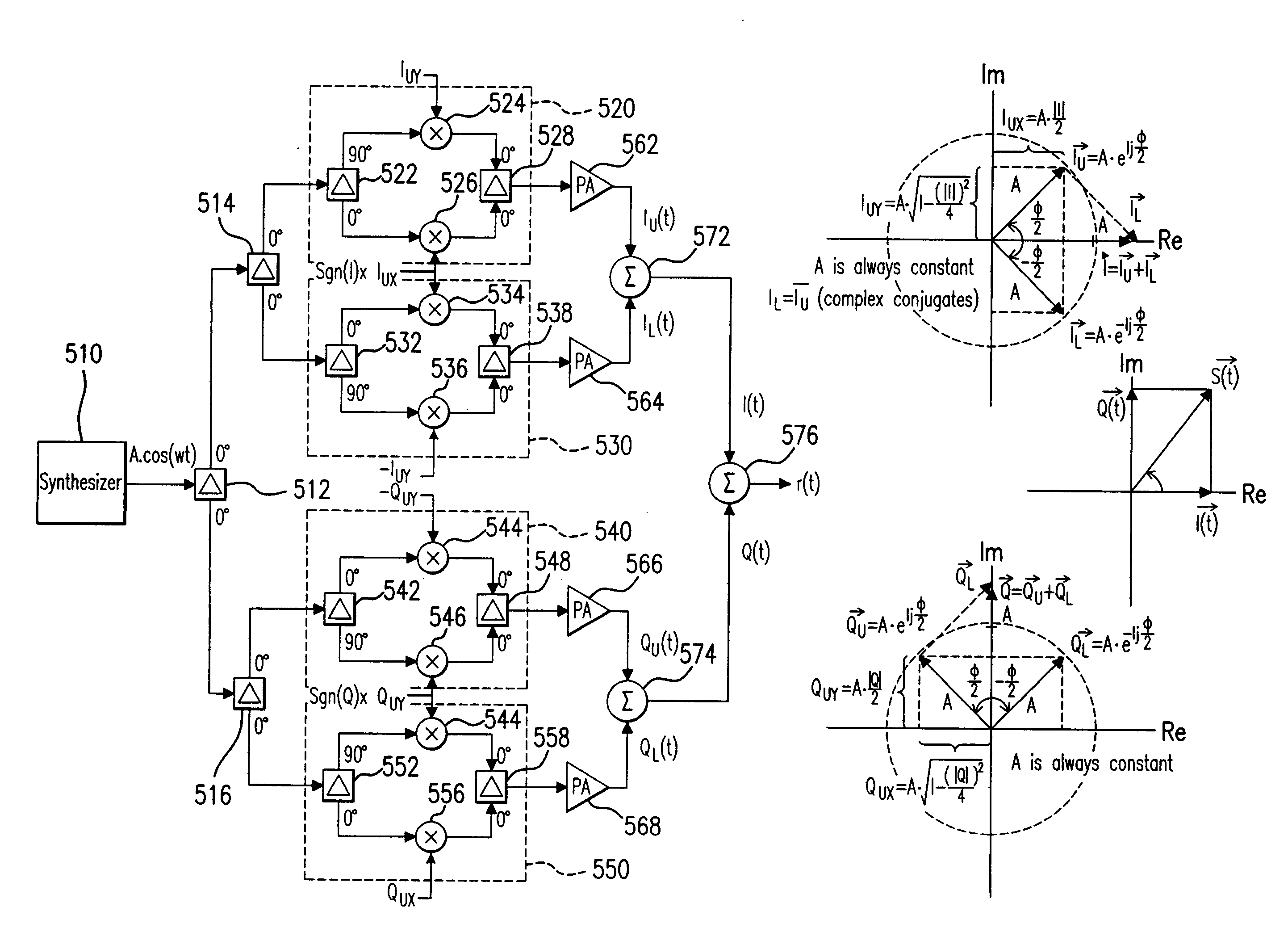
[0357]FIG. 15 is a block diagram that conceptually illustrates an exemplary embodiment 1500 of the Direct Cartesian 2-Branch VPA embodiment. An output signal r(t) of desired power level and frequency characteristics is generated from in-phase and quadrature components according to the Direct Cartesian 2-Branch VPA embodiment.

[0358] In the example of FIG. 15, a clock signal 1510 represents a reference signal for generating output signal r(t). Clock signal 1510 is of the same frequency as that of desired output signal r(t).

[0359] Referring to FIG. 15, exemplary embodiment 1500 includes a first branch 1572 and a second branch 1574. The first branch 1572 includes a vector modulator 1520 and a power amplifier (PA) 1550. Similarly, the second branch 1574 includes a vector modulator 1530 and a power amplifier (PA) 1560.

[0360] Still referring to FIG. 15, clock signal 1510 is input, in parallel, into vector modulators 1520 and 1530. In vector modulator 1520, an in-phase version 1522 of clo...

exemplary embodiment 2000

[0411]FIG. 20 is a block diagram that illustrates an exemplary embodiment 2000 of a transfer function module, such as transfer function modules 710 and 712 of FIG. 7A, implementing the process flowchart 1900. In the example of FIG. 20, transfer function module 2000 receives I and Q data signals 2010 and 2012. In an embodiment, I and Q data signals 2010 and 2012 represent I and Q data components of a baseband signal, such as signals 702 and 704 in FIG. 7A.

[0412] Referring to FIG. 20, in an embodiment, transfer function module 2000 samples I and Q data signals 2010 and 2012 according to a sampling clock 2014. Sampled I and Q data signals are received by components 2020 and 2022, respectively, of transfer function module 2000. Components 2020 and 2022 measure, respectively, the magnitudes of the sampled I and Q data signals. In an embodiment, components 2020 and 2022 are magnitude detectors.

[0413] Components 2020 and 2022 output the measured I and Q magnitude information to components...


PUM


Abstract

Methods and systems for vector combining power amplification are disclosed herein. In one embodiment, a plurality of signals are individually amplified, then summed to form a desired time-varying complex envelope signal. Phase and / or frequency characteristics of one or more of the signals are controlled to provide the desired phase, frequency, and / or amplitude characteristics of the desired time-varying complex envelope signal. In another embodiment, a time-varying complex envelope signal is decomposed into a plurality of constant envelope constituent signals. The constituent signals are amplified equally or substantially equally, and then summed to construct an amplified version of the original time-varying envelope signal. Embodiments also perform frequency up-conversion.

Description

CROSS-REFERENCE TO RELATED APPLICATIONS [0001] The present application is a continuation of pending U.S. patent application Ser. No. 11 / 508,989 filed Aug. 24, 2006 (Atty. Dkt. No. 1744.2160001), which claims the benefit of U.S. Provisional Patent Application No. 60 / 794,121 filed on Apr. 24, 2006 (Atty. Dkt. No. 1744.2140000), U.S. Provisional Patent Application No. 60 / 797,653 filed on May 5, 2006 (Atty. Dkt. No. 1744.2150000), and U.S. Provisional Patent Application No. 60 / 798,705 filed on May 9, 2006 (1744.2160000), and is also a continuation-in-part of U.S. patent application Ser. No. 11 / 256,172, filed Oct. 24, 2005 (Atty. Dkt. No. 1744.1900006), which claims the benefit of U.S. Provisional Patent Application No. 60 / 620,972 filed on Oct. 22, 2004 (Atty. Dkt. No. 1744.1900000), U.S. Provisional Patent Application No. 60 / 671,542 filed on Apr. 15, 2005 (Atty. Dkt. No. 1744.1960000), U.S. Provisional Patent Application No. 60 / 671,536 filed on Apr. 15, 2005 (Atty. Dkt. No. 1744.1970000...

Claims


Application Information

Patent Timeline
Patent Type & Authority Applications(United States)
IPC IPC(8): H03F3/60
CPCH03F1/32H03F3/211H03F3/24H03F3/38H03F2200/102H03F2201/3206H03G3/3042H03F1/02H03F1/0205H03F1/0211H03F1/0261H03F1/0294H04B1/04
Inventor SORRELLS, DAVID F.RAWLINS, GREGORY S.RAWLINS, MICHAEL W.
Owner PARKER VISION INC
Why Eureka
Try Eureka