Method for estimating number of tags in slotted aloha-based RFID system

a technology of slotted aloha and rfid system, which is applied in the field of method for estimating the number of tags in the slotted aloha-based rfid system, can solve the problems of wasting slots, unable to identify, and collisions

Inactive Publication Date: 2007-05-03
ELECTRONICS & TELECOMM RES INST
View PDF5 Cites 44 Cited by
  • Summary
  • Abstract
  • Description
  • Claims
  • Application Information

AI Technical Summary

Benefits of technology

The present invention provides a way to count the number of tags in a specific type of wireless communication called RFID. This is done by measuring things like how many empty spaces there are between the tags or what kind of data they use. By analyzing these measurements, we're able to come up with a more accurate way to track the numbers of different tags.

Problems solved by technology

This patent discusses the technical problem addressed in the RFID technology, specifically related to identifying multiple tags without colliding during communication within a limited amount of time. The issue arises due to the fact that the RFID system does not always accurately estimate the number of tags present in the field of view of the reader. Consequently, there may be too few or too many slots assigned to each tag, resulting in decreased system efficiency.

Method used


Image

  • Method for estimating number of tags in slotted aloha-based RFID system
  • Method for estimating number of tags in slotted aloha-based RFID system
  • Method for estimating number of tags in slotted aloha-based RFID system

Examples


Embodiment Construction

[0017] Other objects and aspects of the invention will become apparent from the following description of the embodiments with reference to the accompanying drawings, which is set forth hereinafter.

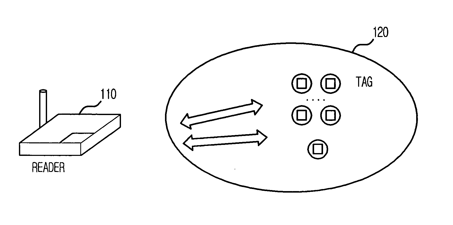
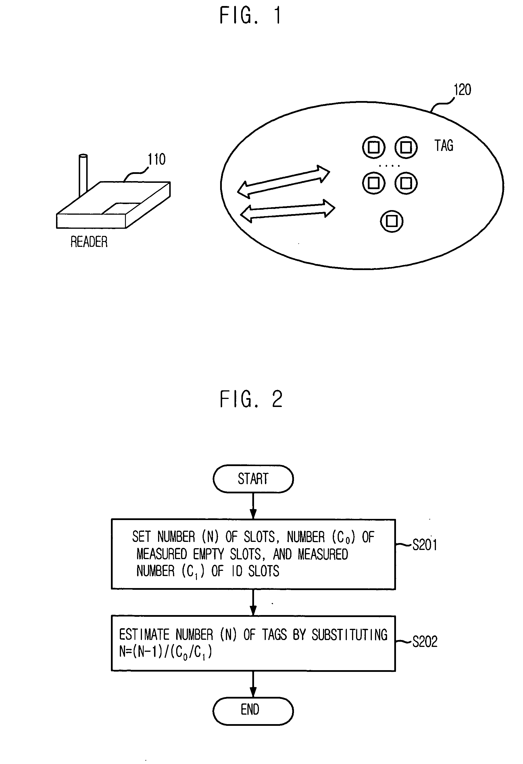
[0018]FIG. 1 is a view of an RFID system in accordance with an embodiment of the present invention.

[0019] Referring to FIG. 1, the RFID system includes a tag 120 having unique ID information, and a reader 110 for recognizing the tag and reading the ID information from the recognized tag.

[0020] Hereinafter, a method for estimating the number of tags in a slotted Aloha-based RFID system in accordance with the preferred embodiments of the present invention will be described in detail. The existing studies on the estimation of the number of tags within a predetermined region will be first described and a new statistical average method will be then described. Moreover, the comparison and simulation results of the present invention and the prior art will be described.

[0021] Regarding the exi...


PUM


Abstract

Provided is a method for estimating the number of tags in a slotted Aloha-based RFID system, which can estimate the number of tags through a new statistical average scheme using the number of slots, the measured number of empty slots, and the measured number of ID slots. The estimating method includes the steps of: a) setting the number (N) of slots, the measured number (c0) of empty slots, and the measured number (c1) of ID slots as parameters; and estimating the number (n) of the tags by substituting the set values into n=(N−1)/(c0/c1).

Description


Claims


Application Information

Patent Timeline
Owner ELECTRONICS & TELECOMM RES INST
Why Eureka
Try Eureka