
Data processing method, data processing apparatus, mask generation method, and mask pattern

a data processing apparatus and mask technology, applied in the field of data processing apparatus, can solve the problems of unsatisfactory reduction of beading density and uneven density in print images, and achieve the effect of reducing the viscosity of the treatment liquid and reducing the degradation of the image resulting from beading

Active Publication Date: 2007-05-03
CANON KK
View PDF11 Cites 37 Cited by
  • Summary
  • Abstract
  • Description
  • Claims
  • Application Information

AI Technical Summary

Benefits of technology

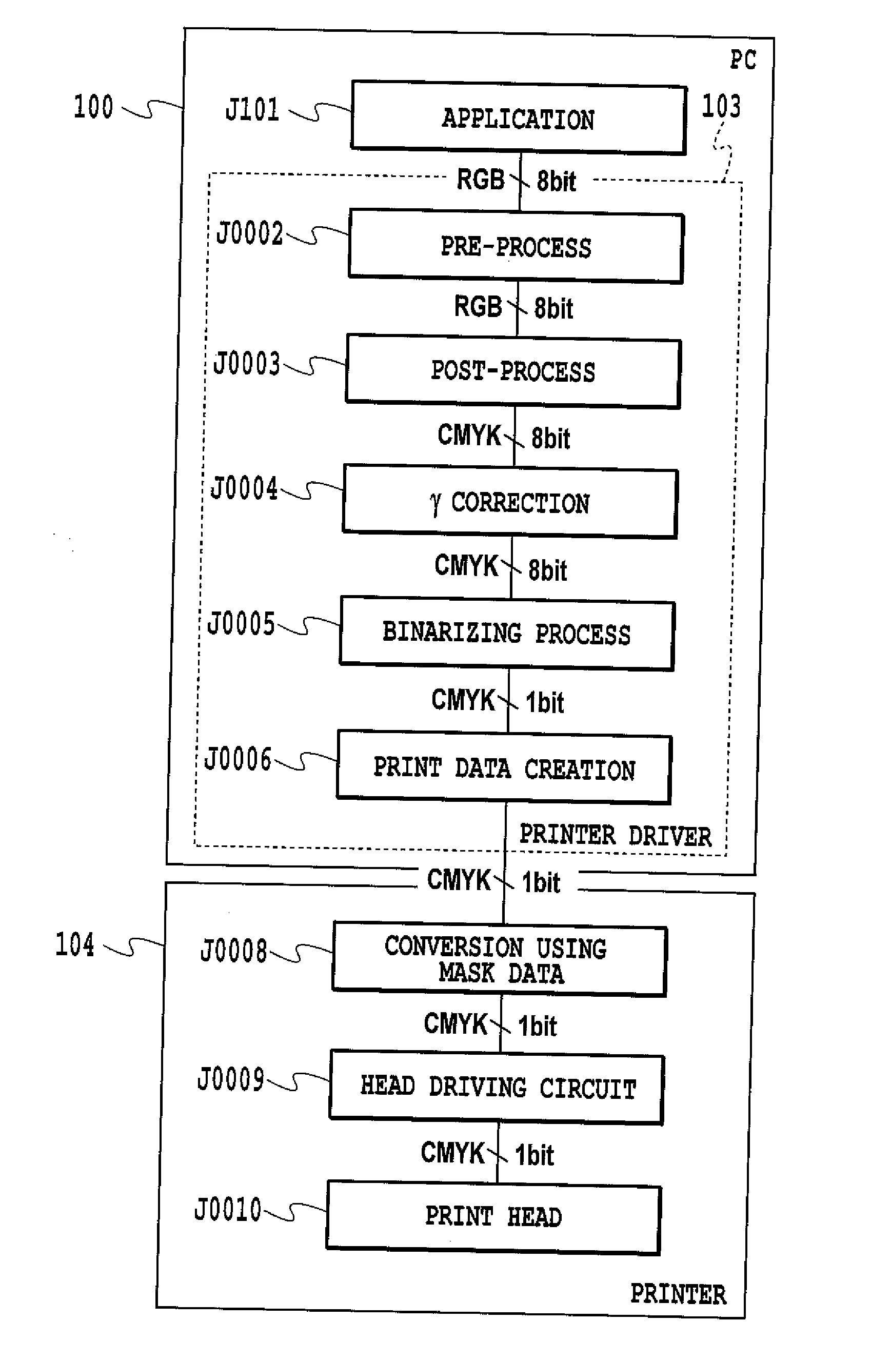
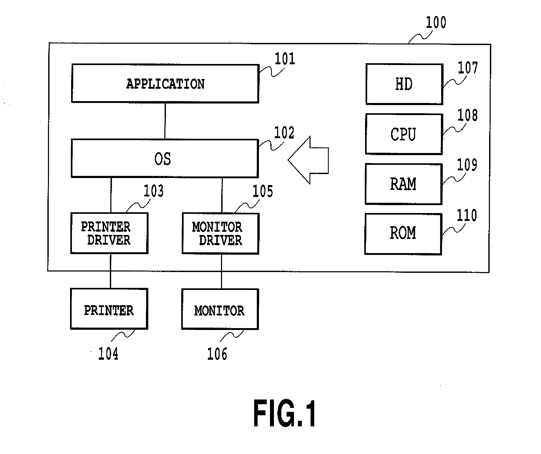
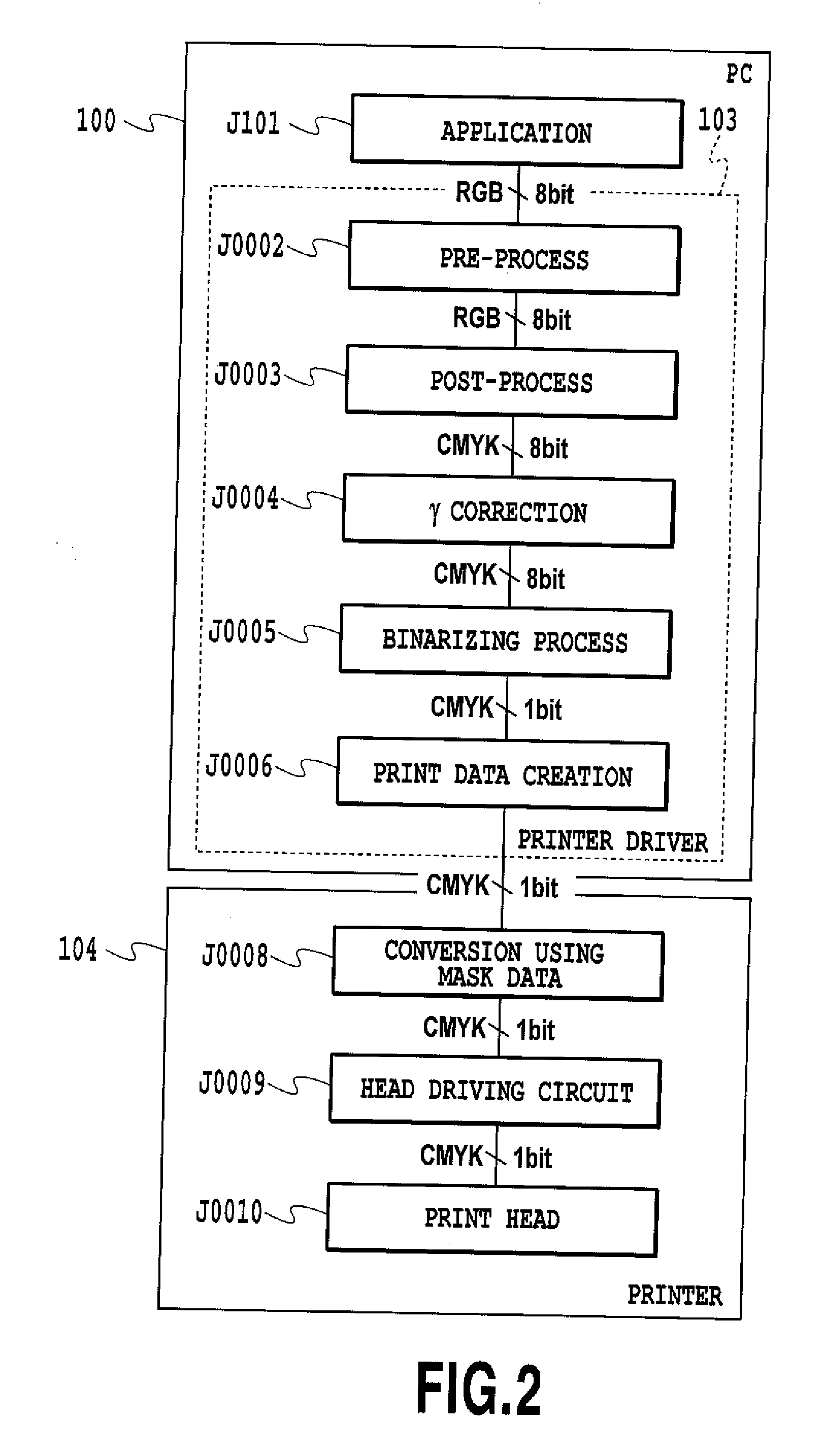
The present invention aims to solve the problem of beading, which refers to uneven density in inkjet printing caused by the accumulation of ink droplets on the print medium. The invention provides a method for generating mask patterns that are used to generate image data that causes plural types of dots to be printed by respective scans. The mask patterns are designed to disperse the print permitting pixels and reduce the likelihood of beading. The invention also addresses the issue of grains, which can be formed during divided printing and cause image quality degradation. The method includes determining the arrangement of print permitting pixels in the mask patterns so that low frequency components decrease in the mask patterns. Overall, the invention provides a solution for improving the quality of inkjet printing and reducing beading.

Problems solved by technology

Thus, a more than ever important problem is beading, in which extra inks that cannot be absorbed by a print medium contact and connect to each other on the medium to cause uneven density in a print image.
However, beading cannot be sufficiently reduced simply by using different mask patterns for the respective colors.

Method used


Image

  • Data processing method, data processing apparatus, mask generation method, and mask pattern
  • Data processing method, data processing apparatus, mask generation method, and mask pattern
  • Data processing method, data processing apparatus, mask generation method, and mask pattern

Examples


embodiment 1

[0160] 100% Even Mask for Two Pass Printing

[0161] (1) Summary of the Embodiment

[0162] The present embodiment relates to two pass multi-pass printing in which an image is completed by two times of scanning operations of the print heads for each of the cyan (C), magenta (M), yellow (Y), and black (K) ink. For each of the ink colors used for the two pass printing, not only a mask (hereinafter referred to a “1 plane” mask) for each of plural scans (in the present embodiment, two scans) but also an arbitrary combination of plural planes of these masks is appropriately dispersed.

[0163]FIG. 4 is a diagram schematically showing print heads, mask patterns, and a print medium to describe the two pass printing. In the description of the figure, for simplification of illustration and description, the two pass printing is executed using three colors, cyan, magenta, and yellow. This also applies to the masks described below.

[0164] Each group of color nozzles for cyan, magenta, and yellow is d...

embodiment 3

[0332] 100% Gradation Mask for Two Pass Printing

[0333] The present embodiment relates to what is called a gradation mask. The gradation mask is known from, for example, Patent Document 3. The gradation mask shows a print rate varying depending on the nozzle position such that a lower print rate is set for the ends of a nozzle array, while a higher print rate is set for the center of the nozzle array. This mask is effective in improving image grade by relatively reducing the frequency of ejections from the end nozzles which may affect the boundary between the print areas of the respective passes in multi-pass printing.

[0334] The “print rate” of the mask pattern refers to the ratio of the number of print permitting pixels to the number of all the pixels (the sum of the print permitting pixels and print non-permitting pixels) contained in a given area in a mask pattern. For example, the print rate of the mask pattern corresponding to a single nozzle refers to the ratio of the number ...

embodiment 4

[0370] 150% Even Mask for Two Pass Printing

[0371] In the above embodiments, plural plane masks of the same color are complementary to one another, and the arrangements of the print permitting pixels on plural planes are exclusive to one another. The application of the present invention is not limited to these masks. The present invention is also applicable to plural planes of masks of the same color which have a total print rate of more than 100%. Masks with a print rate of more than 100% enable an increase in maximum ink ejection amount even with the low resolution of image data.

[0372] A fourth embodiment of the present invention relates to masks for which two planes of the same color which are used for two pass printing each have a print rate of 75% and a total print rate of 150%.

[0373]FIG. 84 is a schematic diagram conceptually illustrating the masks for the two pass printing. In FIG. 84, P0001 denotes a print head for one of the colors C, M and Y. Here, for simplification of ...


PUM


Abstract

The present invention provides a mask for divided printing that completes an image by plural scans using inks of different plural inks, the mask being able to suppress possible grains during printing to reduce image degradation resulting from beading. If for example, among the print permitting pixels for which the total repulsive potential is to be calculated, a print permitting pixel Do has the highest total repulsive potential, changes in repulsive potential after movement of the pixels are determined and the print permitting pixel Do is moved to a pixel having the lowest total repulsive potential after the movement. This processing is repeated to enable a reduction in the total energy of the entire plane. Consequently, the print permitting pixels are appropriately dispersed in overlapping plane masks so as to have few low frequency components.

Description

[0001] This application is a continuation application of PCT application No. PCT / JP2005 / 012514 under 37 Code of Federal Regulations § 1.53 (b) and the said PCT application claims the benefit of Japanese Patent Application Nos. 2004-199623, filed Jul. 6, 2004 and 2005-197873, filed Jul. 6, 2005, which are hereby incorporated by reference herein in their entirety.BACKGROUND OF THE INVENTION [0002] 1. Field of the Invention [0003] The present invention relates to a data processing method, a data processing apparatus, a mask generating method, and a mask pattern, and more specifically, to mask processing or a mask pattern for generating dot print data for dividedly forming ink dots constituting a print image by means of plural scans of a print head. [0004] 2. Description of the Related Art [0005] Ink jet printers widely employ what is called a multi-path printing system. The multi-path printing system is a system that dividedly forms ink dots constituting an arbitrary area in an image b...

Claims


Application Information

Patent Timeline
Patent Type & Authority Applications(United States)
IPC IPC(8): B41J2/205
CPCG06K15/107B41J29/38
Inventor MARUMOTO, YOSHITOMO
Owner CANON KK
Learn More