Smart destination image routing system

a destination image and routing system technology, applied in the field of image routing systems, can solve the problems of not being desirable to transmit images or images, increasing workflow times, and generally not becoming effective, and achieve the effect of quick and easy change of settings

Inactive Publication Date: 2007-05-03
PENRAD TECH
View PDF19 Cites 9 Cited by
  • Summary
  • Abstract
  • Description
  • Claims
  • Application Information

AI Technical Summary

Benefits of technology

[0011] A feature and advantage of the present invention is that users need not open and manually edit the code in a configuration file to route images and change destinations. The system according to the various embodiments of the present invention can include a destination configuration editor that utilizes a graphical user interface (“GUI”) through which a user can quickly and easily change the settings.
is that users need not open and manually edit the code in a configuration file to route images and change destinations. The system according to the various embodiments of the present invention can include a destination configuration editor that utilizes a graphical user interface (“GUI”) through which a user can quickly and easily change the settings.

Problems solved by technology

The change generally does not become effective until the configuration file has been saved and the program has been restarted.
This can lead to increased workflow times.
In particular situations, however, it may not be desirable to transmit the image or images to every SCP that is identified and defined on the network.
This can lead to inefficient management of the SCPs and unnecessary increases in network traffic.
This can potentially lead to significant turnaround times to send and / or receive scanned images.

Method used


Image

  • Smart destination image routing system
  • Smart destination image routing system
  • Smart destination image routing system

Examples


Embodiment Construction

[0021] The smart destination image router according to the present invention provides increased efficiency and workflow when transmitting DICOM images. The increased efficiency can be achieved by enabling a user to quickly turn destinations on or off and by creating criteria for each SCU, thus dictating the default circumstances under which the destinations will receive the images. Opening and editing configuration code to make destination changes is therefore unnecessary.

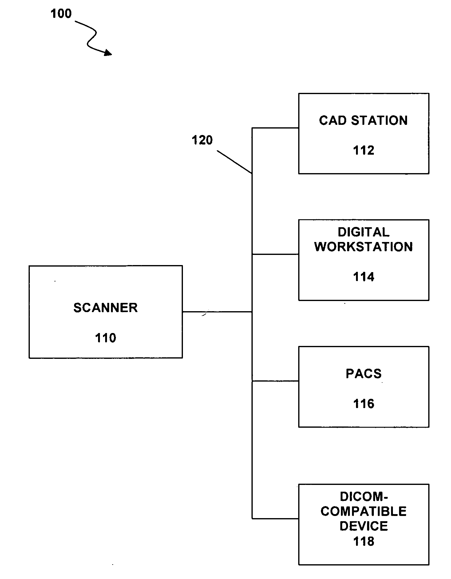
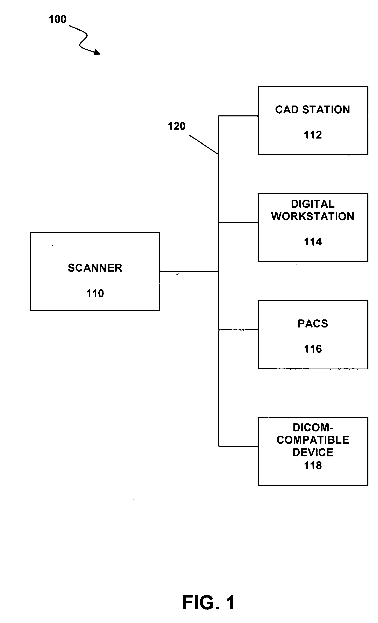
[0022] Referring to FIG. 1, a medical imaging system 100 according to one example embodiment comprises a scanner 110, a computer-aided diagnosis (CAD) system 112, a digital workstation 114, a picture archiving and communications system (PACS) 116, and one or more other DICOM-compatible device 118. Devices 110, 112, 114, 116, and 118 are generally mammogram image handling devices, wherein the mammogram images can be hardcopy films, digital mammogram image files, or both, depending upon the function and compatibilit...


PUM


Abstract

A smart destination image scanning and routing system and a method of routing digital mammogram images. The system and method can include a configuration editor that utilizes a graphical user interface (“GUI”) through which a user can quickly and easily turn image destinations on or off by creating criteria for each destination, thus dictating the default for circumstances under which the destinations will receive the images. Users therefore need not open and manually edit the code in a configuration file to route and reroute images.

Description

RELATED APPLICATION [0001] This application claims the benefit of U.S. Provisional Application No. 60 / 731,650, filed Oct. 28, 2005, which is incorporated herein by reference in its entirety.COMPACT DISC [0002] A compact disc containing codes and information describing a preferred embodiment of the present invention is submitted herewith and is hereby incorporated by reference. The compact disc contains the following files and / or programs: TitleSize in BytesDate of CreationDICOMDestination.txt7,123Oct. 27, 2005DICOMG.txt30,670Oct. 27, 2005DlgMain.txt122,233Oct. 27, 2005frmEditDestination.txt11,633Oct. 27, 2005SmartDestination.txt13,687Oct. 27, 2005SmartDestinationEditor.txt1,151Oct. 27, 2005FIELD OF THE INVENTION [0003] The present invention relates generally to image routing systems. More particularly, the present invention relates to a mammogram image routing system for a mammogram image scanner that enables a user to select and modify the destinations to which scanned mammogram i...

Claims


Application Information

Patent Timeline
Patent Type & Authority Applications(United States)
IPC IPC(8): G06K9/00G16H30/20G16H40/63
CPCG06F19/321H04L67/327G16H40/63G16H30/20H04L67/63
Inventor GUSTAFSON, GREGORY A.
Owner PENRAD TECH
Why Eureka
Try Eureka