Syringe plunger driver system

a technology of syringe and driver, which is applied in the direction of suction devices, intravenous devices, other medical devices, etc., to achieve the effect of convenient loading of syringe plungers in relation to the plunger driver and accurate detection

Active Publication Date: 2007-05-03
CAREFUSION 303 INC
View PDF14 Cites 61 Cited by
  • Summary
  • Abstract
  • Description
  • Claims
  • Application Information

AI Technical Summary

Benefits of technology

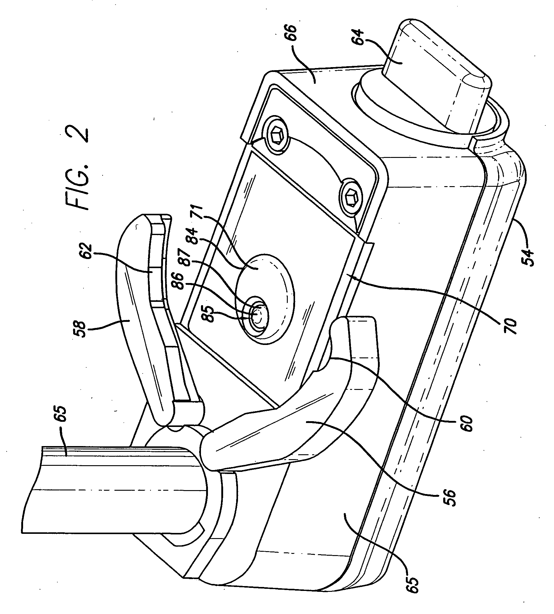
[0013] In other aspects, the bias device comprises a spring connected with the plunger retainer that biases the arms pivotally inward towards each other, the spring having enough force to retain a plunger flange in between the arms during the operation mode. The driver system further comprises a force detector located in the plunger driver and adapted to sense force exerted by the pushing surface against the plunger flange, the force detector outputting a force signal representative of the force exerted against the plunger flange. In more detailed aspects, the force detector is in contact with the pushing surface, the pushing surface comprises a movable flange contact plate, and the movable flange contact plate is pivotally mounted. Further, the driver system comprises a processor in communication with the force signal that compares the force signal against a threshold and provides an alarm signal if the force signal exceeds the threshold. In one embodiment, the syringe plunger driver system further comprises a force concentrator located on the plunger driver that defines the pushing surface, whereby force exerted against the plunger flange in operation mode is concentrated at the pushing surface of the force concentrator so that the force may be accurately detected.
[0014] In another aspect of the invention, a method is provided for capturing syringe plungers of different sizes at a plunger driver, each plunger having a plunger piston, a plunger flange, and a plunger stem interconnecting the piston with the flange, wherein each plunger forms a part of a syringe, each syringe having a barrel in which the plunger moves, each plunger flange having an inner side facing the syringe barrel and an outer side, the plunger driver adapted to move the syringe plunger into the syringe barrel in an operation mode, the method comprising the steps of opening first and second asymmetric arms mounted to the plunger driver away from each other far enough to permit easy loading of a syringe plunger to the plunger driver and, after a syringe plunger has been properly positioned in relation to the plunger driver, closing the first and second arms inward toward each other to capture the syringe plunger flange between the first and second arms. In a more detailed aspect, the step of closing the arms comprises the step of closing the first and second arms inward toward each other such that a tip of one of the arms moves into a notch on an inside edge of the other of the arms so that a syringe plunger flange of a relatively small size may be captured by the first and second arms. In another detailed aspect, the step of opening first and second asymmetric arms further comprises the step of rotating a rotation knob interconnected with the first and second arms to a first rotation position at which the rotation knob pivotally moves the first and second arms outward into a syringe plunger non-engagement position whereby easy loading of a syringe plunger in relation to the plunger driver is facilitated and, further, the step of closing the first and second arms inward toward each other comprises the steps of applying a biasing force to the first and second arms to bias them inward toward each other and moving the rotation knob to a second rotation position at which the rotation knob does not apply force opposing the biasing devices on the first and second arms so that the arms may move toward each other to capture a syringe plunger.

Problems solved by technology

Further, the control device comprises a rotation knob having a first rotation position at which it moves the first and second arms outwardly into the syringe plunger non-engagement position in opposition to the first bias device, and a second rotation position at which the rotation knob does not prevent the first and second arms from capturing the syringe plunger flange.

Method used


Image

  • Syringe plunger driver system
  • Syringe plunger driver system
  • Syringe plunger driver system

Examples


Embodiment Construction

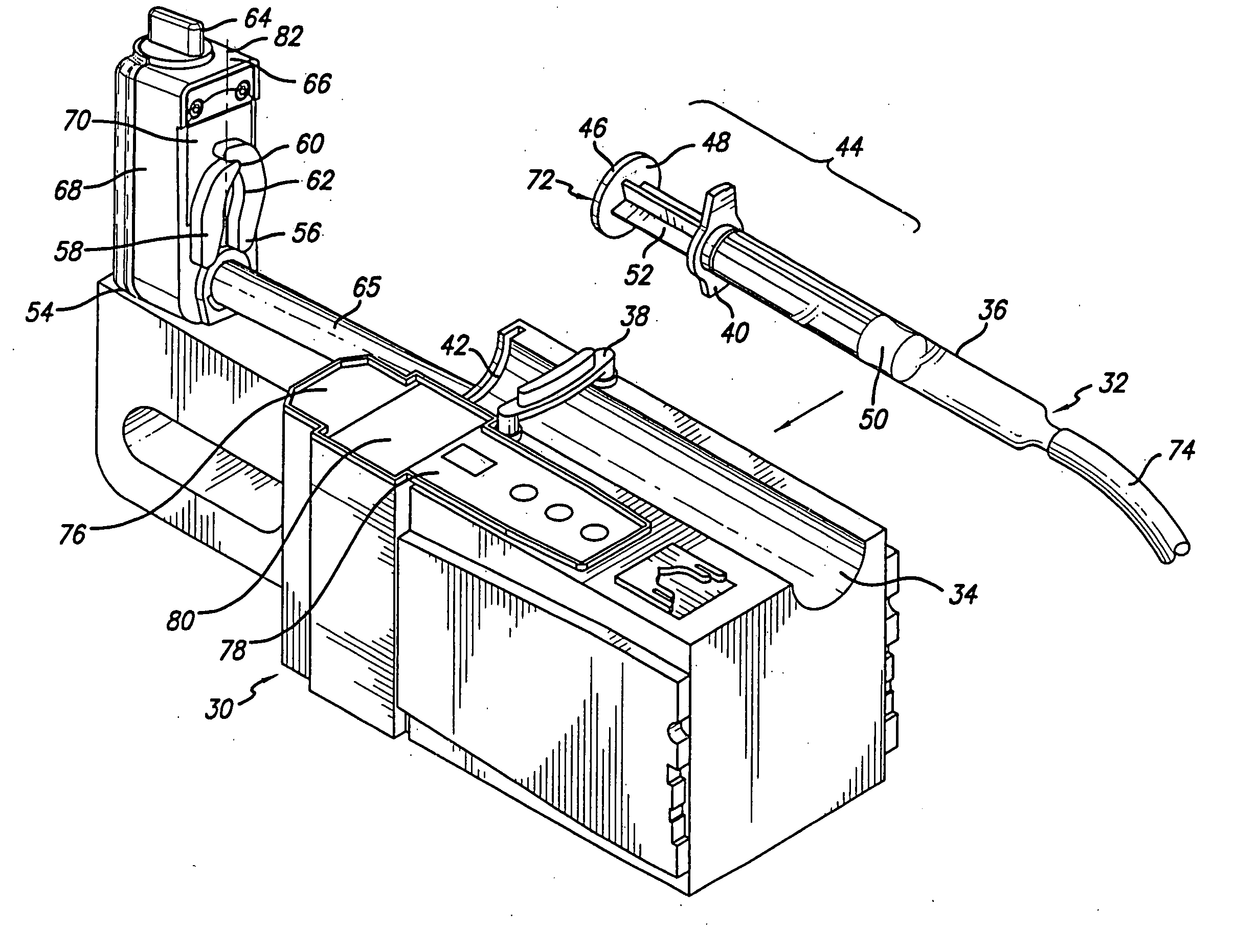
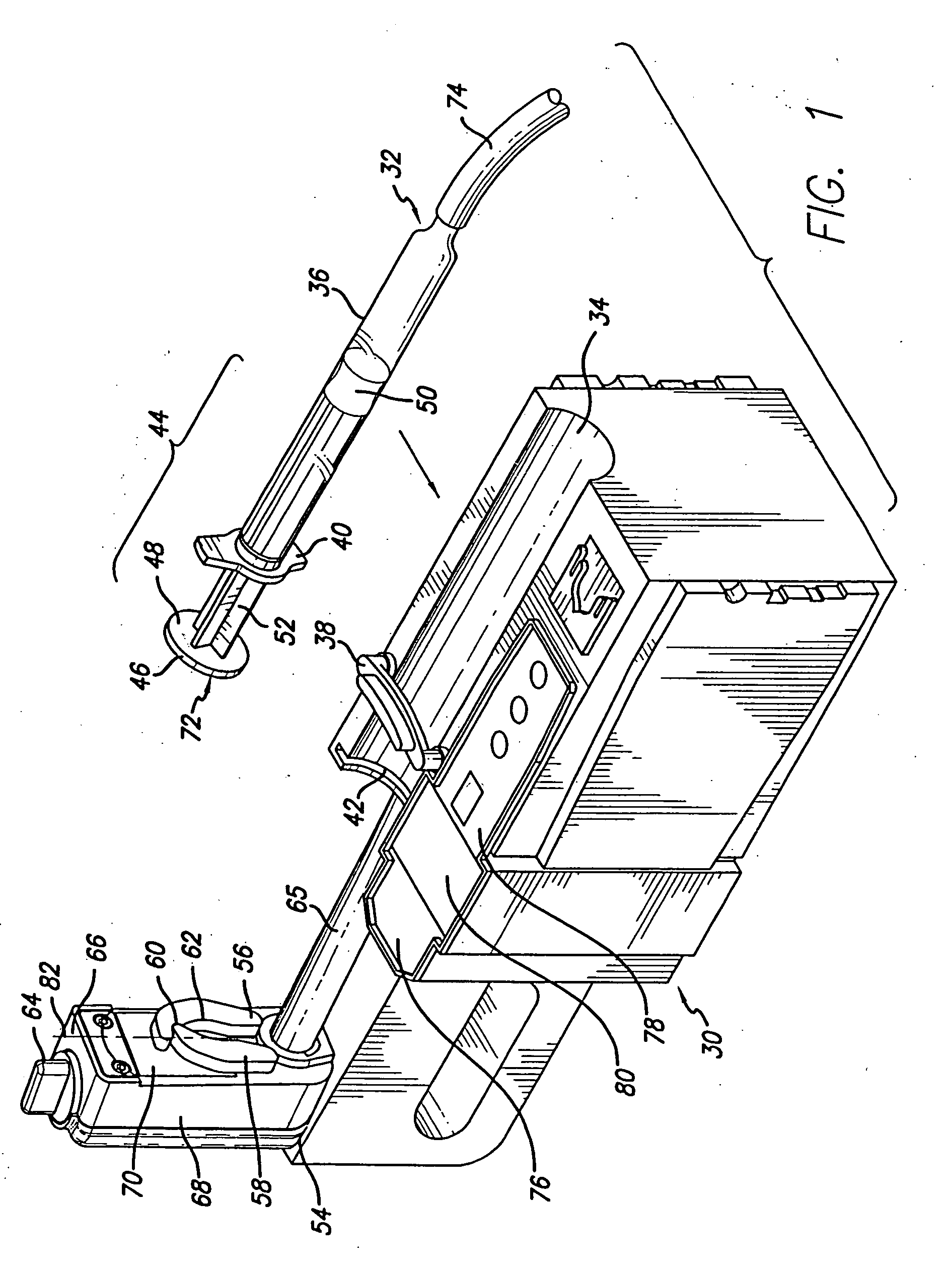
[0028] Referring now to the drawings with more particularity, wherein like reference numerals designate like or corresponding elements among the several views, there is shown in FIG. 1 a perspective view of a syringe pump 30 having a syringe plunger driver system in accordance with the principles of the invention. A syringe 32 is shown next to the pump rather than mounted in the pump, for clarity of illustration, with an arrow indicating the mounting location. The syringe pump 30 includes a syringe cradle 34 in which the syringe barrel 36 will rest when properly mounted in the pump. The cradle 34 includes a syringe barrel clamp 38 to securely hold the syringe barrel 36 in a fixed position in the cradle 34 so that lateral movement is resisted. The syringe barrel clamp 38 is pivoted in this embodiment so that it may be moved into an open position to permit loading or removal of a syringe and a closed position in which it extends over the cradle 34 to hold a mounted syringe barrel 36. ...


PUM

PropertyMeasurementUnit
distanceaaaaaaaaaa
anglesaaaaaaaaaa
travel distanceaaaaaaaaaa

Abstract

A syringe plunger driver system capable of capturing syringes of widely varying sizes comprises a pair of asymmetric plunger retainer arms pivotally mounted to a plunger driver. The system includes a low profile driver having a length that exceeds its width so that it may be mounted adjacent control modules and other operational modules. The arms are biased toward each other and one arm is longer than the other with a notch on an inside edge to receive the tip of the shorter arm when capturing small syringe flanges. A rotation knob mounted to the front surface of the low profile driver forces the arms apart when rotated to a first rotation position. A force sensor is mounted in the driver to detect occlusions in the fluid line. A processor monitors the force sensed by the force sensor and provides an alarm if the force exceeds a threshold. The driver includes a force concentrator that defines a pushing surface adapted to press against a plunger flange so that the force applied to the plunger flange is concentrated at a defined location for more accurate measurement.

Description

BACKGROUND [0001] The invention is related generally to drive mechanisms for medical infusion pumps, and more particularly, to a system and method for driving the plunger of a syringe in a syringe pump. [0002] The infusion of medical fluids, such as parenteral fluids, into the human body is accomplished in many cases by means of a syringe pump in which a syringe containing the parenteral fluid is mounted. Syringe pumps typically secure the syringe barrel in a fixed position and push or “drive” the syringe plunger into the barrel at a controlled rate to expel the parenteral fluid. A fluid administration set conducts the expelled parenteral fluid from the syringe barrel to the patient. Many syringe pumps have an elongated lead screw rotated by a motor and a screw drive mechanism such as a split nut that translates the rotational motion of the lead screw into linear motion. A syringe plunger driver is connected to the screw drive mechanism and to the syringe plunger for driving the plu...

Claims


Application Information

Patent Timeline
Patent Type & Authority Applications(United States)
IPC IPC(8): A61M37/00A61M31/00A61M1/00A61M5/145
CPCA61M5/1452A61M5/1456A61M5/1458A61M2205/18Y10T29/49776Y10T29/49771Y10T29/49769Y10T29/49826A61M2202/0007
Inventor MORRIS, MATTHEW G.SCHWARTZ, DONALD F.
Owner CAREFUSION 303 INC
Why Eureka
Try Eureka