

Load carrier for motor vehicles
a technology for motor vehicles and load carriers, applied in vehicle components, transportation and packaging, supplementary fittings, etc., can solve the problem of limiting the possibility of integrating load carriers into the contour of vehicles, and achieve the effect of simple design and robustness
- Summary
- Abstract
- Description
- Claims
- Application Information
AI Technical Summary
Benefits of technology
Problems solved by technology
Method used
Image

Examples
Embodiment Construction
)
[0026] In the figures, elements that are the same and elements having the same function are labeled with the same reference numbers.
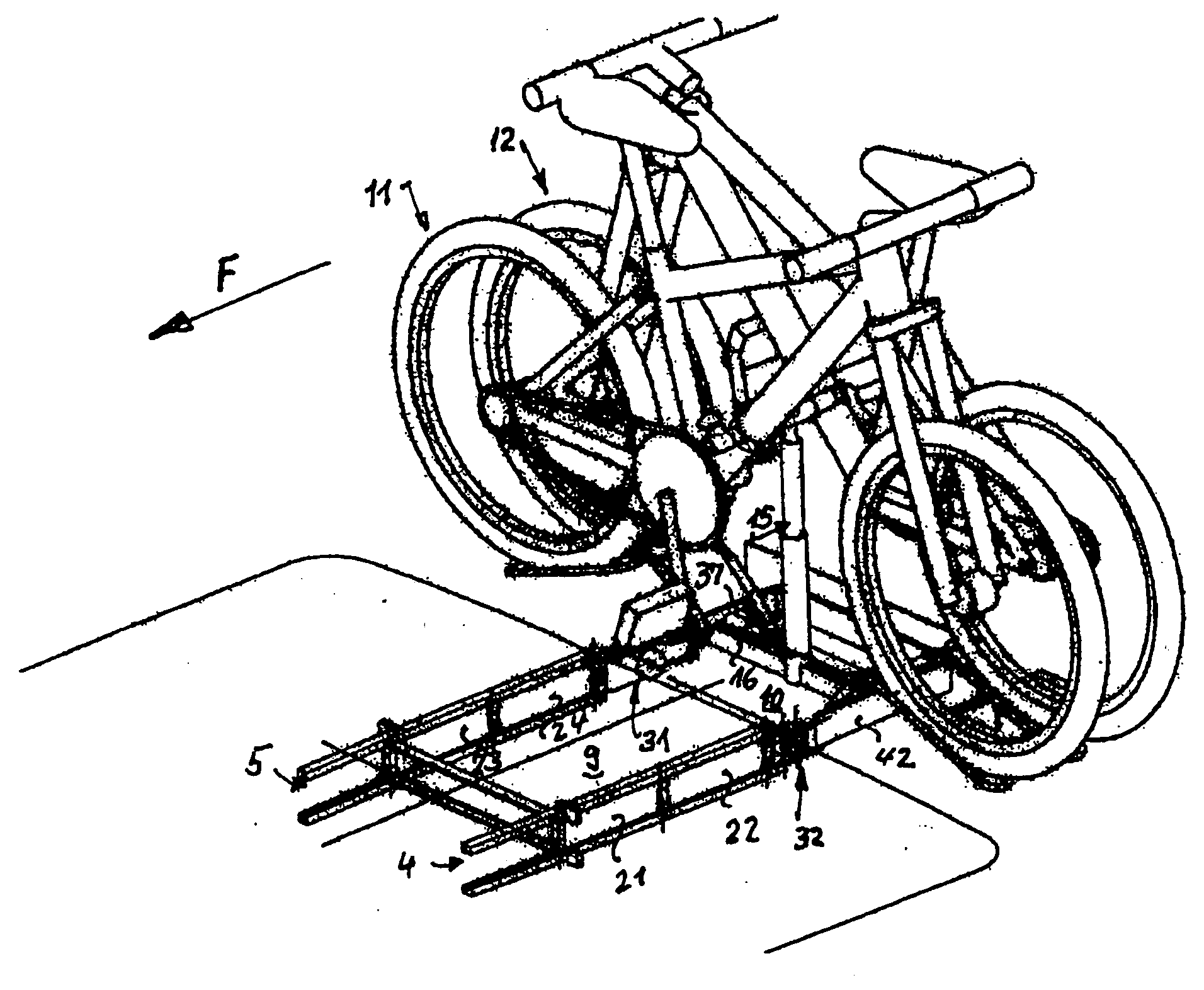
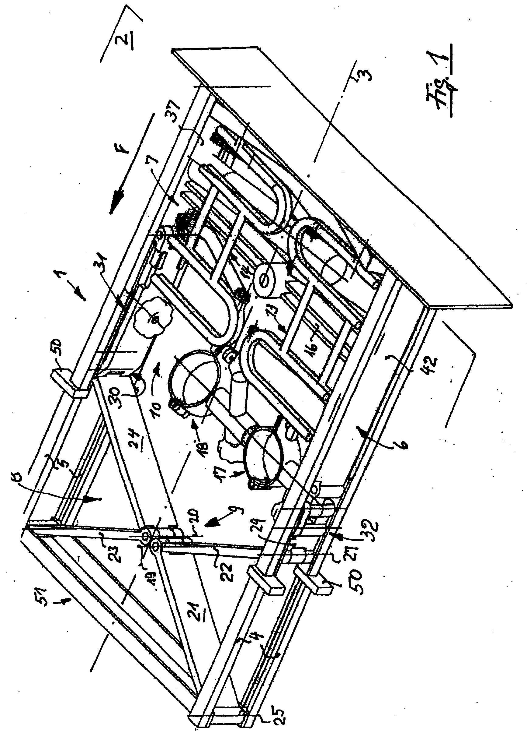
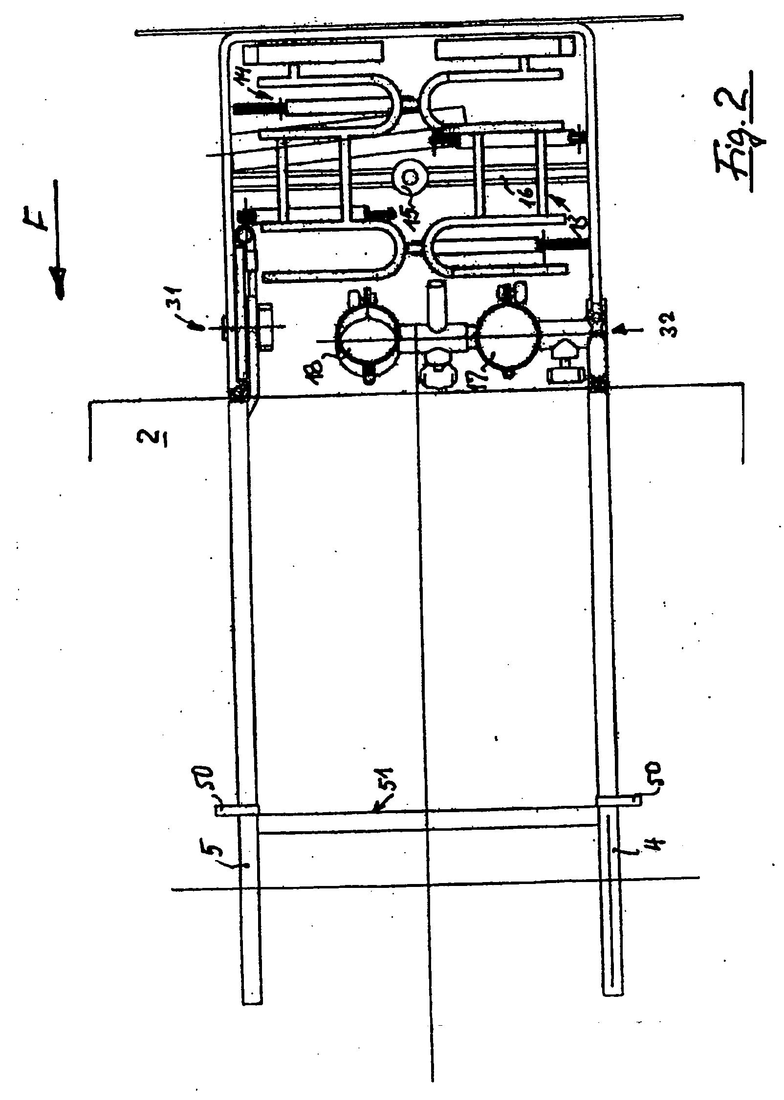
[0027] With references to the Figures, a load carrier 1 for a motor vehicle 2 in accordance with an embodiment of the present invention is shown. Motor vehicle 2 is preferably a passenger vehicle such as a sport-utility vehicle. Load carrier 1 is to be situated in the longitudinal center of the bottom region of vehicle 2 and extendable at the rear. The contour of vehicle 2 is illustrated in the Figures with the longitudinal center axis of vehicle 2 denoted by reference numeral 3.
[0028] Load carrier 1 is fixed to vehicle 2. Load carrier 1 includes guides 4, 5 on each longitudinally extending side of load carrier 1. Guides 4, 5 extend parallel to longitudinal center axis 3. Load carrier 1 includes a support frame 8 having a pair of longitudinally extending carrier structures 6, 7. Carrier structures 6, 7 are laterally spaced apart from one another. Car...
PUM
 Abstract
Description
Claims
Application Information