Method and an apparatus for simultaneous 2D and 3D optical inspection and acquisition of optical inspection data of an object

a technology of optical inspection and optical data acquisition, applied in the direction of measuring devices, instruments, scientific instruments, etc., can solve the problems of inaccurate corresponding between, affecting the quality of optical inspection, so as to achieve the effect of enhancing the quality of imag

Active Publication Date: 2007-05-10
NIDEC-READ CORPORATION
View PDF38 Cites 20 Cited by
  • Summary
  • Abstract
  • Description
  • Claims
  • Application Information

AI Technical Summary

Benefits of technology

[0009] Applicant has found that by using methods or an apparatus as defined above, it is possible to carry out simultaneous 2D and 3D scanni...

Problems solved by technology

Processing sequentially the 2D and 3D inspections is a source of technical difficulties, such as inaccurate corresponding between 2D and 3D images associated with...

Method used


Image

  • Method and an apparatus for simultaneous 2D and 3D optical inspection and acquisition of optical inspection data of an object
  • Method and an apparatus for simultaneous 2D and 3D optical inspection and acquisition of optical inspection data of an object
  • Method and an apparatus for simultaneous 2D and 3D optical inspection and acquisition of optical inspection data of an object

Examples


Embodiment Construction

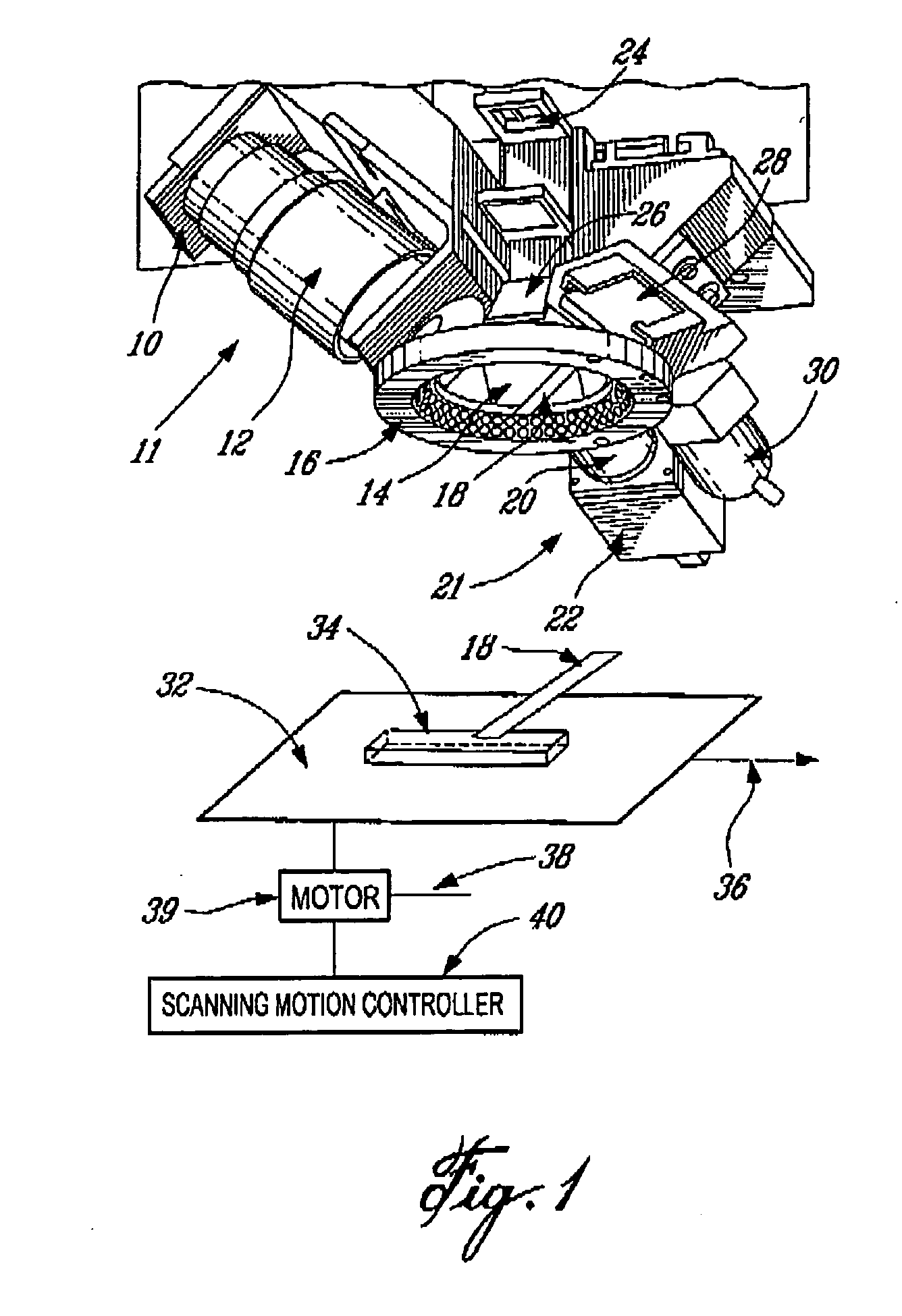
[0023] Referring first to FIG. 1 and FIG. 4, there is shown an optical inspection system wherein the 2D and 3D optical scanning are carried out simultaneously without interference. First, the object being inspected, in the embodiment shown a wafer having bumps, 34 is deposed on a mobile stage 32 that moves with a given speed in a predetermined direction 36, so that the object being inspected 34 passes in the 2D scanning system field of view 23 and in the 3D scanning system field of view 25. The mobile stage 32 is linked to a motor 38 that is controlled by a scanning motion controller 40. Controller 40 controls the speed of the mobile stage 32 as a function of the scan resolution.

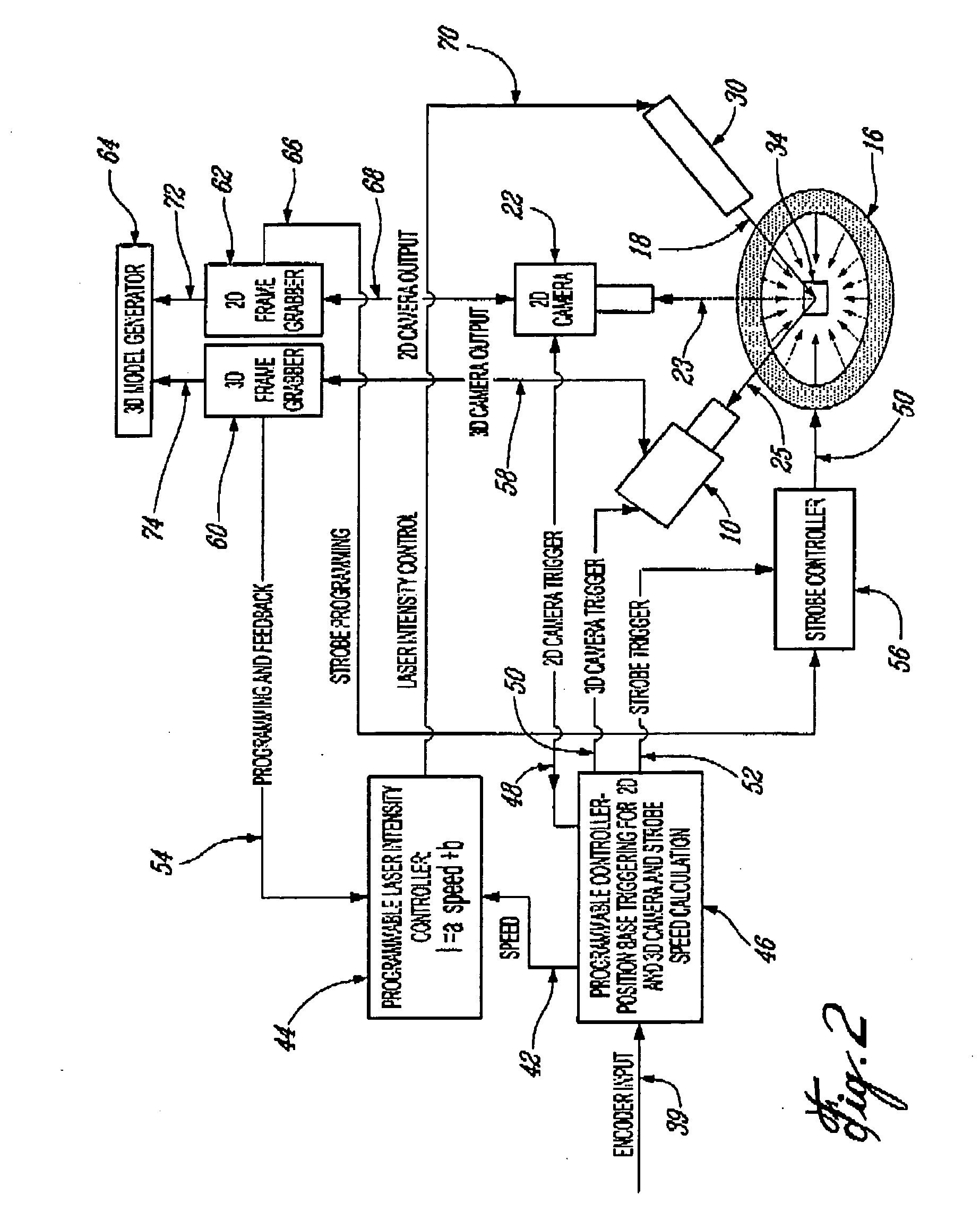
[0024] The optical inspection system comprises a 2D scanning system 21 for 2D image acquisition and a 3D scanning system 11 for profile line data acquisition. In the 2D scanning system 21, a mirror 26 reflects the image of the object being inspected 34 inside a 2D lens 20 that, in turn, conveys the reflecte...


PUM


Abstract

The present invention relates to optical inspection of manufactured products, such as integrated circuits wafer bumps. There are provided methods and apparatus for acquisition of optical inspection data of said object, as well as for optical inspection and manufacturing of said object. The invention comprises a 2D optical scanning system and a 3D optical scanning system that can have common image trigger control and/or operate simultaneously without interference to have the same field of view.

Description

FIELD OF THE INVENTION [0001] The invention relates to optical inspection of manufactured products, such as integrated circuits wafer bumps. BACKGROUND OF THE INVENTION [0002] Traditionally, in the field of optical inspection of integrated circuits wafer bumps, 2D inspection was carried out first and then 3D inspection was carried out after the first inspection. In this traditional embodiment, the 2D camera system works in a free run mode at the maximum possible speed while the scanning speed is kept constant and in function of the camera speed and the optical field of view. Mainly, the 2D subsystem consisted of one of the following. The first system was a TDI type camera employing a constant light source while scanning speed is tightly controlled so that the resulting image on the TDI sensor travels across the sensor at the sensor shifting speed enabling the light integration over multiple sensor line. This synchronous speed allows, depending on the length of the TDI sensor, much h...

Claims


Application Information

Patent Timeline
IPC IPC(8): G01B11/30G01N21/00
CPCG01N21/9501G01B11/0608
Inventor VODANOVIC, BOJKO
Owner NIDEC-READ CORPORATION
Why Eureka
Try Eureka