Developer bearing member, developing device, process cartridge and image forming apparatus

a technology of developing device and bearing member, which is applied in the direction of electrographic process apparatus, instruments, optics, etc., can solve the problems of large amount of stress applied to the developer, deformation of the developer bearing roller in the manufacturing process, and poor developer bearing ability of the developing roller

Inactive Publication Date: 2007-05-10
RICOH KK
View PDF29 Cites 30 Cited by
  • Summary
  • Abstract
  • Description
  • Claims
  • Application Information

AI Technical Summary

Benefits of technology

[0018] As a further aspect of the present invention, an image forming apparatus is provided which includes a latent image bearing member and the above-mentioned developing device which develops a latent image on the latent image bearing member with a developer including a toner to form a toner image on the latent image bearing member. The image forming apparatus preferably includes one or more of the process cartridge mentioned above.

Problems solved by technology

When the roughness of the sandblasted surface of the developing rollers is too small, the developing rollers have poor developer bearing ability.
When the roughness of the surface of the developing rollers is increased to improve the developer bearing ability thereof, a problem which occurs is that the developer bearing rollers are deformed in the manufacturing process.
The developing rollers having plural V-form grooves extending in a direction parallel to the rotation axis thereof have a drawback in that a large amount of stress is applied to the developer on the surface of the developing rollers when (the edge of) each of the plural grooves passes above (or below) a developer layer forming member.
In addition, the developing rollers having plural V-form grooves have another drawback in that the amount of developer in the peripheral direction (i.e., the rotation direction) of the developing rollers varies when the shapes (such as depth) of the grooves vary, resulting in formation of uneven density images.
When such slanting grooves are formed on the surface of a developing roller, a problem in that the developer bearing ability of the developing roller deteriorates after long repeated use occurs depending on the conditions of the slanting grooves.
Further, a problem in that an undesired horizontal stripe image having a horizontal high-density portion at regular intervals is formed occurs depending on the conditions of the slanting grooves.
Furthermore, a problem in that an undesired vertical stripe image having a vertical high density portion at regular intervals is formed occurs depending on the conditions of the slanting grooves.

Method used


Image

  • Developer bearing member, developing device, process cartridge and image forming apparatus
  • Developer bearing member, developing device, process cartridge and image forming apparatus
  • Developer bearing member, developing device, process cartridge and image forming apparatus

Examples


example 1

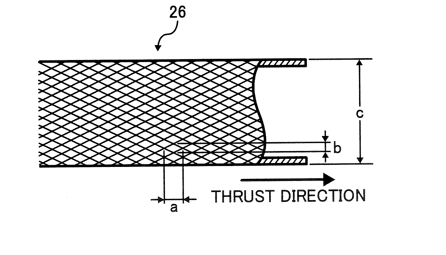
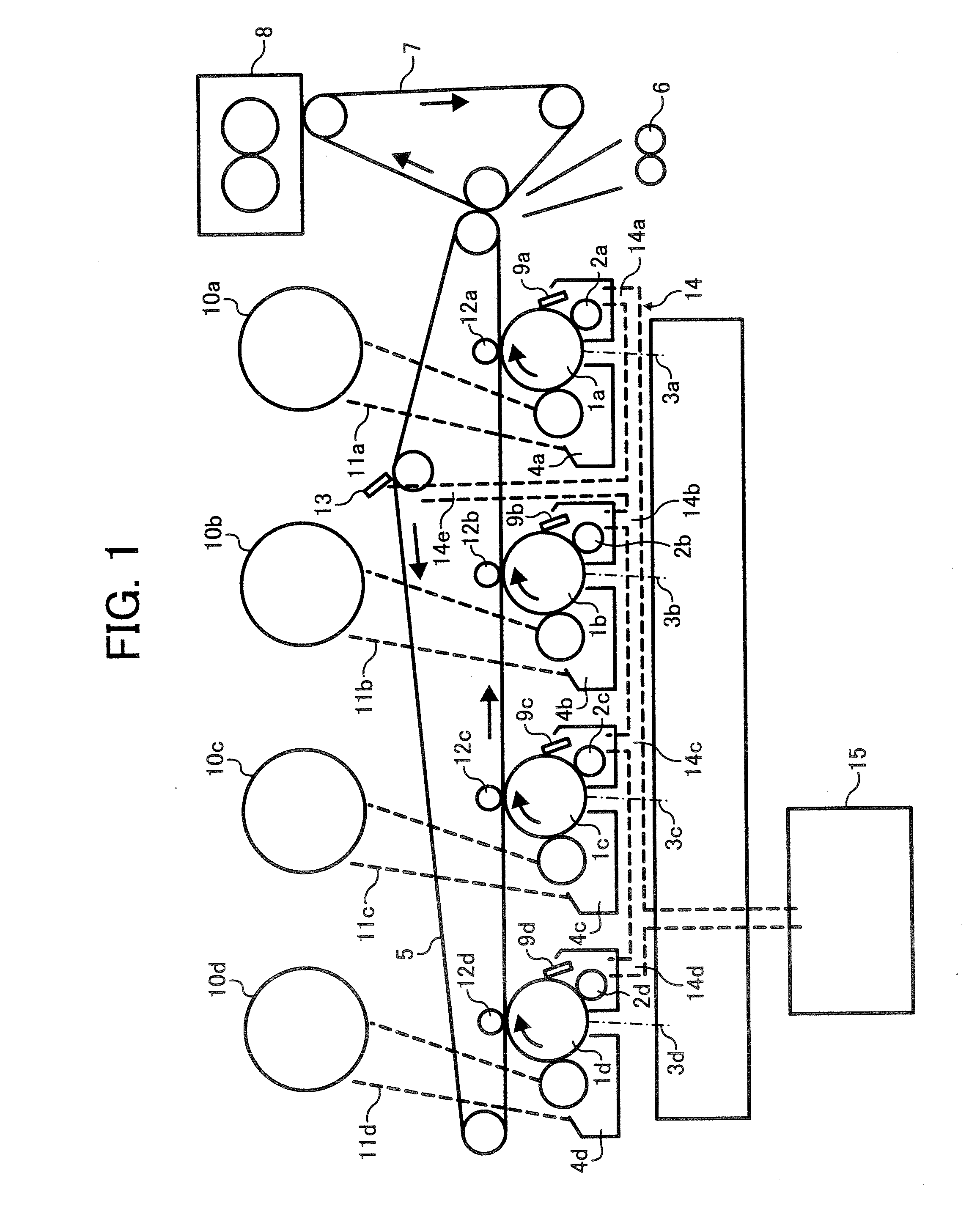
[0092] When the following developing roller was used for the image forming apparatus illustrated in FIG. 1, good images without horizontal stripe images were produced. [0093] Diameter of developing roller: 18 mm [0094] First intersection distance (a): changed in a range of from 1.3 mm to 4.8 mm. [0095] Second intersection distance (b): changed in a range of from 0.75 mm to 2.2 mm.

[0096] The linear velocities of the developing sleeve and the photoreceptor were set to be 290 m / s and 150 mm / s, respectively.

[0097] As a result, the developing rollers having grooves having a slanting angle of from 15° to 40° could bear a proper amount of developer thereon in the above-mentioned range during the test in which 160,000 copies are produced.

[0098] Another embodiment of the developer bearing member will be explained referring to drawings.

[0099]FIG. 11A is an enlarged view of a developer bearing member, which may cause the horizontal stripe image problem, and FIG. 11B is an enlarged view of ...

example 2

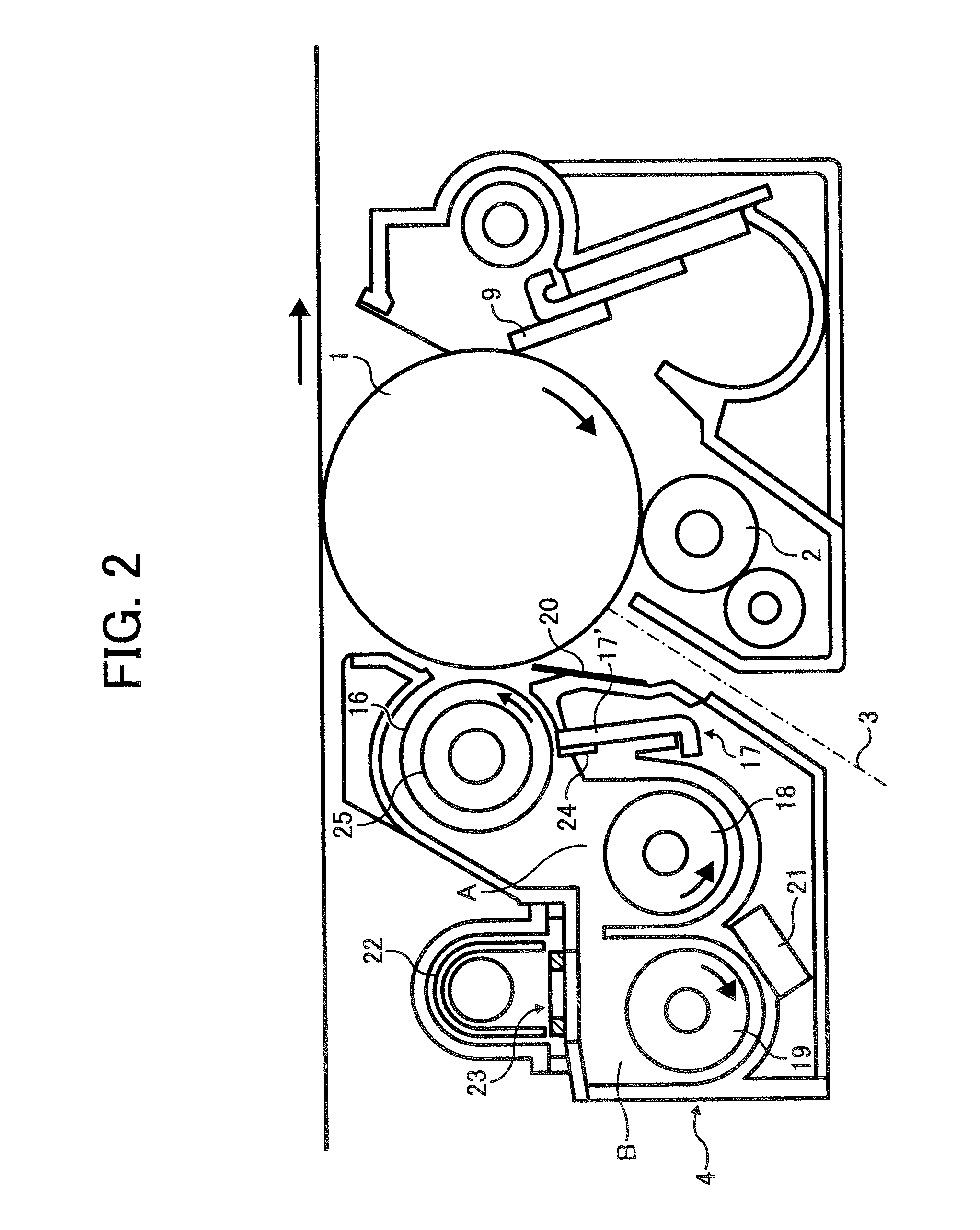
[0104] When the following developing roller was used for the image forming apparatus illustrated in FIG. 1, good images without horizontal stripe images were produced. [0105] Diameter of developing roller: 18 mm [0106] Number of grooves: 80 (40+40 (reversely slanting grooves)) [0107] Slanting angle (θ or θ′): 25°[0108] Angle of vertical wall of groove: 90°[0109] Width of groove: 240 μm [0110] Depth of groove: 90 μm [0111] Weight of developer drawn by sleeve: 48 mg / cm2 (±8 mg / cm2) [0112] Doctor gap: 0.34 mm [0113] Gap between surface of developing sleeve and surface of photoreceptor (development gap): 0.3 mm (±0.05 mm)

[0114] Next another embodiment of the developer bearing member will be explained.

[0115]FIG. 15 is a schematic view for explaining how to determine the deviation of depth of grooves. At first, the developing roller 16 is rotated while both the ends of the rotation shaft of the roller are supported. The distance between a point of the surface of the developing roller an...


PUM


Abstract

A developer bearing member on which grooves slanting in a thrust direction of the developer bearing member cross other grooves reversely slanting relative to the thrust direction, wherein each of the grooves and the reversely slanting grooves is slanting at an angle of greater than 0° and not greater than 40°. Any two adjacent intersections of the grooves and the reversely slanting grooves in the thrust (or peripheral) direction are preferably on different levels in the peripheral (or thrust) direction. The distance between two adjacent intersections in the thrust direction is preferably from 1.3 mm to 4.8 mm. The distance between two adjacent intersections in the thrust direction is preferably from 0.38 Vd/Vi (mm) to 1.1 Vd/Vi (mm). The deviation in depth of grooves present on a 36° arc surface portion of the member is not greater than 15% of the gap between the image bearing member and the developer bearing member.

Description

BACKGROUND OF THE INVENTION [0001] 1. Field of the Invention [0002] The present invention relates to a developer bearing member for visualizing a latent image using a developer including a toner. In addition, the present invention also relates to a developing device using the developer bearing member, and a process cartridge and an image forming apparatus using the developing device. [0003] 2. Discussion of the Background [0004] Recently, copiers and printers are required to produce high quality images while having a good combination of reliability and stability. In order to satisfy such requirements, it is preferable to form a uniform developer layer on the peripheral surface of the developer bearing member, which is used for developing a latent image, over a long period of time. Therefore, developing rollers, the surface of which is roughened by sandblasting or has plural V-form grooves extending in a direction parallel to the rotation axis of the developing rollers, have been typ...

Claims


Application Information

Patent Timeline
Patent Type & Authority Applications(United States)
IPC IPC(8): G03G15/09
CPCG03G15/0818
Inventor KATOH, SHUNJIMASUDA, KATSUMIYOSHIZAWA, HIDEOHATTORI, YOSHIOKIMURA, HIDEKISAKAI, KIYOTAKANAKAJIMA, KENJIYOSHIDA, KEIICHIAZAMI, AKIRASUZUKI, YUJI
Owner RICOH KK
Why Eureka
Try Eureka