Drawer-type all-in-one card connector

Inactive Publication Date: 2007-05-10
TAI SOL ELECTRONICS
View PDF9 Cites 18 Cited by
  • Summary
  • Abstract
  • Description
  • Claims
  • Application Information

AI Technical Summary

Benefits of technology

[0007] The primary objective of the present invention to provide a drawer-type all-in-one card connector which employs a sliding box thereof to carry one memory card only

Problems solved by technology

If the user inserts two or more memory cards into the housing at the same time accidentally, a reading or writing error may occur to result in malfunction of the card conne

Method used


Image

  • Drawer-type all-in-one card connector
  • Drawer-type all-in-one card connector
  • Drawer-type all-in-one card connector

Examples


Embodiment Construction

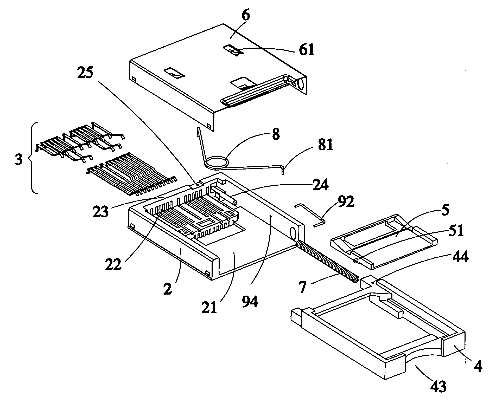
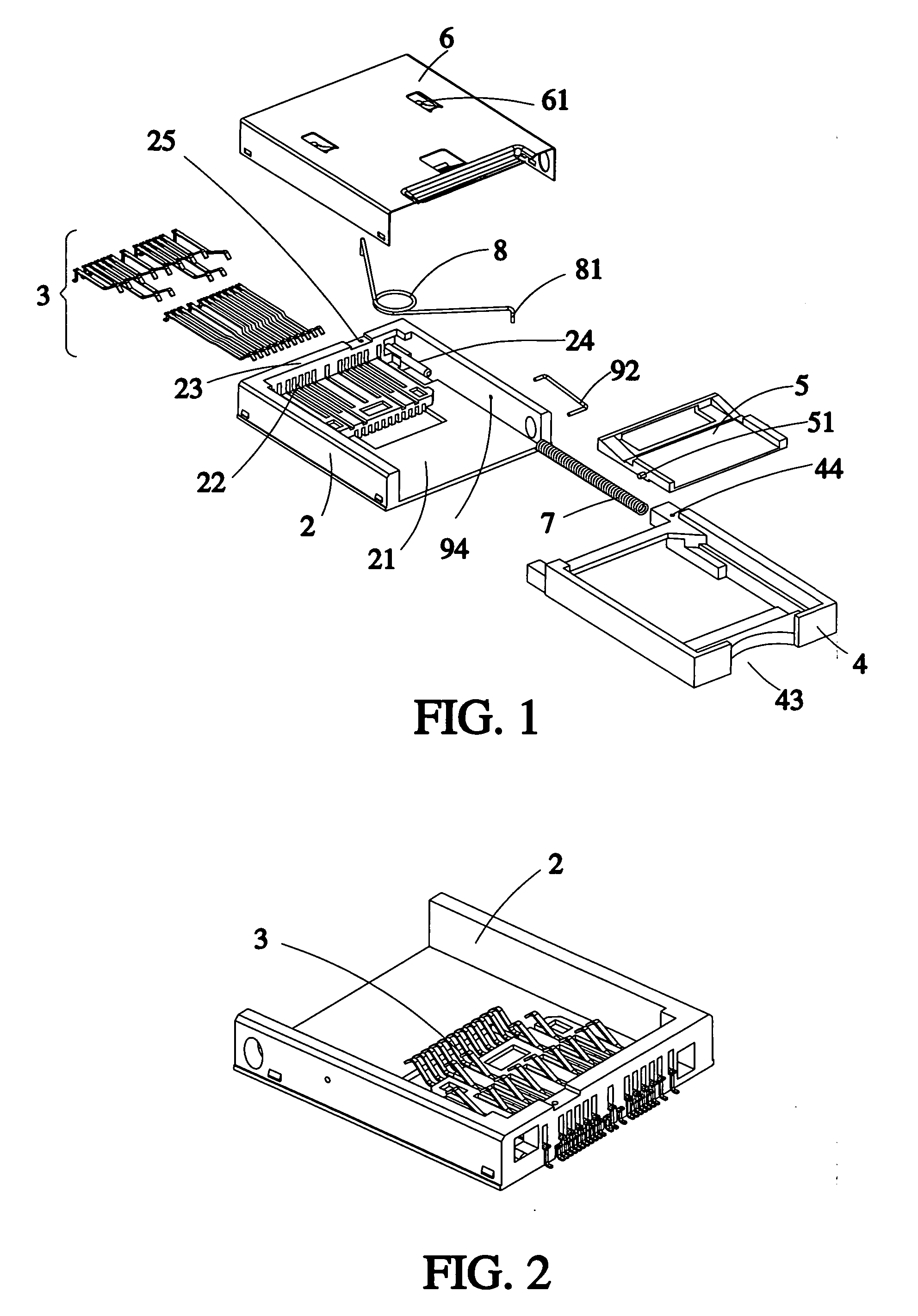
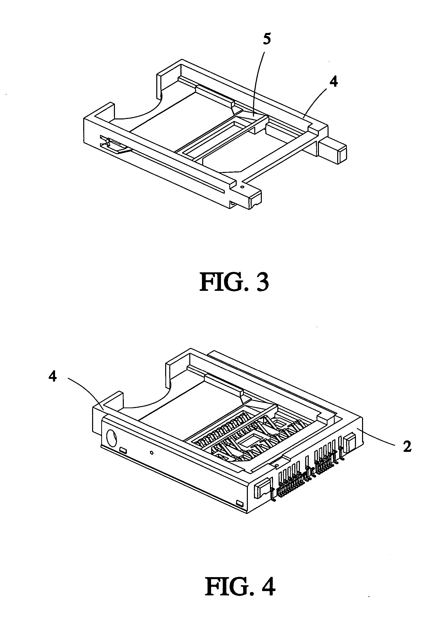
[0035] Referring to FIGS. 1-6, a drawer-type all-in-one card connector in accordance with the present invention is shown comprised of a housing 2, a plurality of card contact terminals 3, a sliding box 4, a movable block member 5, a cover 6, a first ejection spring 7, a second ejection spring 8, and a limiter 9.

[0036] The housing 2 is rectangular, having an upright rear wall 23, an insertion chamber 21, an opening formed at an open end of the insertion chamber, a plurality of sets of terminal slots 22 formed at the other end of the insertion chamber 21 and located on the upright rear wall 23 for mounting the card contact terminals 3, a guide rod 24 forwardly extending from an inner side of the upright rear wall 23 toward the insertion chamber 21, and two positioning holes 25 and 94 formed on a top side of upright rear wall 23. The limiter 11 is located between the housing 2 and the sliding box 4.

[0037] The sliding box 4 is drawer-typed and is slidably mounted in the insertion cham...


PUM


Abstract

A drawer-type all-in-one card connector includes a housing defining an insertion chamber and an opening formed at an end of the insertion chamber and a plurality of terminal slots formed at the other end of the insertion chamber; a plurality of card contact terminals mounted at the terminal slots; a sliding box slidably mounted in the insertion chamber of the housing and having a card receiving chamber for receiving corresponding memory cards of different specifications; a cover covered on the housing; a first ejection spring having two ends contacting against an inner sidewall of the housing and the sliding box respectively; and a limiter provided between the housing and the sliding box.

Description

BACKGROUND OF THE INVENTION [0001] 1. Field of the Invention [0002] The present invention relates to memory card connectors and more particularly, to a drawer-type all-in-one card connector. [0003] 2. Description of the Related Art [0004] A regular card connector is made based on an all-in-one structure capable of receiving different memory cards, i.e., its housing has therein multiple insertion chambers and multiple sets of terminals for receiving different memory cards, such as Memory Stick (MS) card, Smart Media (SM) card, Multi-Media Card (MMC), and Secure Digital (SD) card. [0005] A conventional all-in-one card connector has multiple insertion chambers separately defined without interference, i.e. two or more memory cards can be inserted into the housing at the same time. If the user inserts two or more memory cards into the housing at the same time accidentally, a reading or writing error may occur to result in malfunction of the card connector. Further, when the user inserts ...

Claims


Application Information

Patent Timeline
IPC IPC(8): H01R24/00
CPCH01R13/635H01R13/64H01R27/00
Inventor LAI, YAW-HUEYLWEE, NAI-HOCK
Owner TAI SOL ELECTRONICS
Why Eureka
Try Eureka