Filtration device with a filter bag and a cleaning device for a filter bag

a cleaning device and filter bag technology, applied in the direction of filter regeneration, filtration separation, dispersed particle filtration, etc., can solve the problems of not being able to achieve satisfactory cleaning in all parts of the filter bag, the cleaning of the cleaning device of the cited prior art is much less successful, and the filter bag cannot be mechanically cleaned very well

Inactive Publication Date: 2007-05-17
REINING CHRISTIAN
View PDF11 Cites 6 Cited by
  • Summary
  • Abstract
  • Description
  • Claims
  • Application Information

AI Technical Summary

Benefits of technology

[0013] An object of the present invention is to develop a filtration device of the aforesai

Problems solved by technology

Therefore, cleaning with cleaning devices of the cited prior art is much less successful in this case.
Filter bags cannot be mechanically cleaned very well by the means described above.
This type of jet pulse occurs in an uncontrolled way, with the result that satisfactory cleaning is not obtained in all parts of the bag.
However, a nozzle lance frequently damages the body of the bag, e.g., by cutting it open so that time-consuming operations become

Method used


Image

  • Filtration device with a filter bag and a cleaning device for a filter bag
  • Filtration device with a filter bag and a cleaning device for a filter bag
  • Filtration device with a filter bag and a cleaning device for a filter bag

Examples


Embodiment Construction

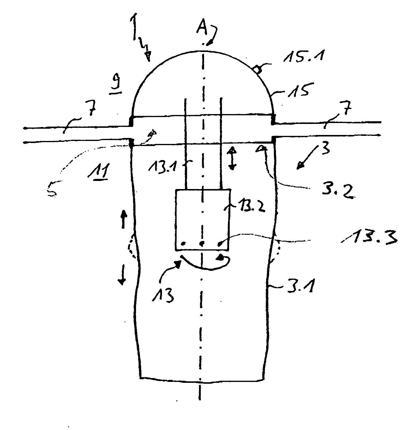
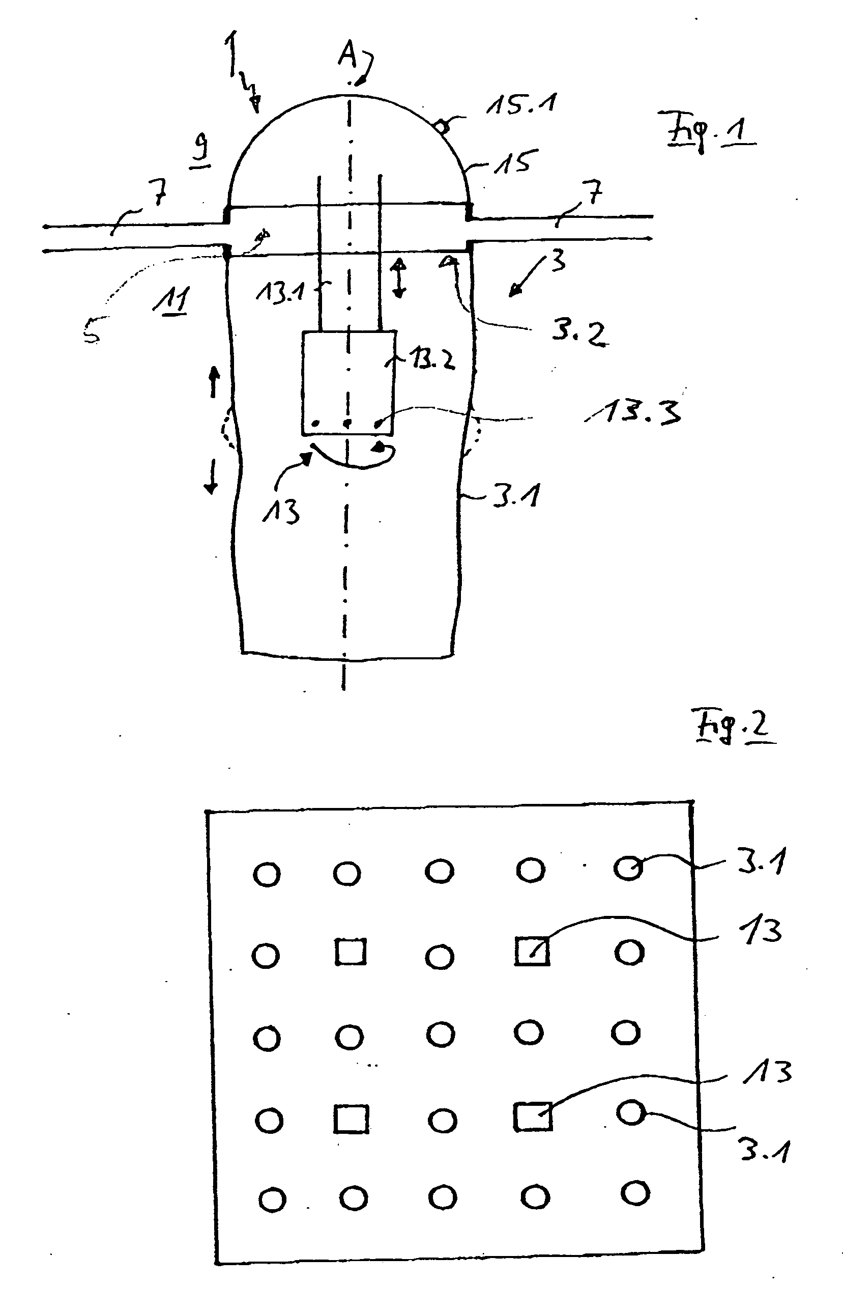
[0033]FIG. 1 shows a schematic view of a filtration device 1 in longitudinal section. The filtration device 1 comprises a filter bag, which has a bag body 3.1 or bag wall that is clamped in an opening 5 of a top plate 7. This clamp mounting results in a bag opening 3.2 over essentially the entire cross section of the clamped bag body 3.1. A clean gas side 9 is located above the top plate 7, and a so-called crude gas side is located below the top plate 7.

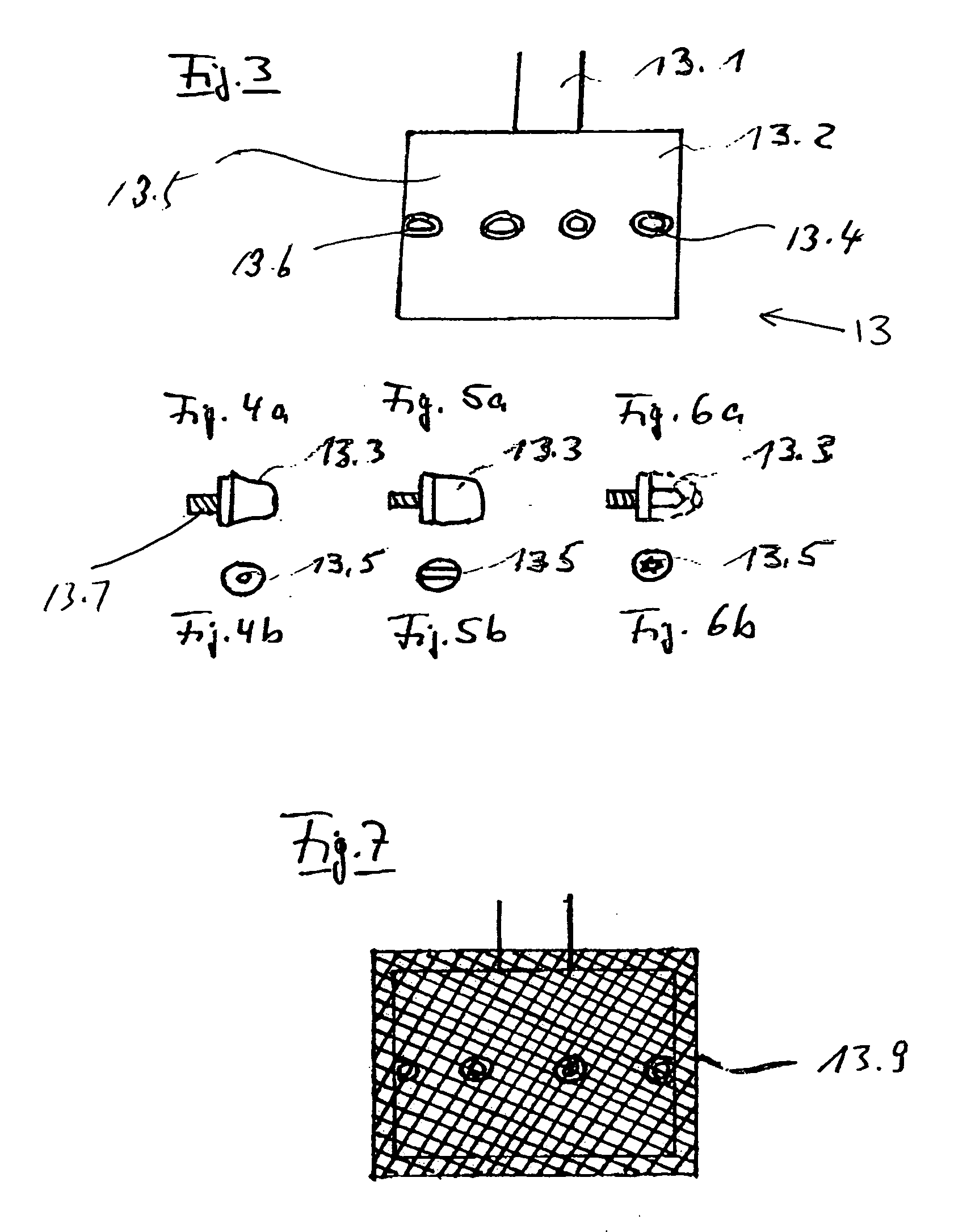
[0034] A cleaning device 13 (shown in detail in FIG. 3) hangs through the bag opening 3.2 and is suspended in the bag body 3.1. In other embodiments, the cleaning device 13 can also be inserted from the crude gas side 11 or from below. The cleaning device 13 comprises essentially a rod-shaped support 13.1 and a nozzle head 13.2 on a free end that extends into the bag body 3.1 along the longitudinal axis of the bag body 3.1. FIG. 1 shows how a plurality of nozzles 13.3 is provided on the nozzle head 13.2. The nozzles 13.3 are arrange...


PUM

PropertyMeasurementUnit
Pressureaaaaaaaaaa

Abstract

A filtration device having at least one filter bag between a crude gas side and a clean gas side, and a cleaning device for cleaning the filter bag. Each filter bag has a bag body with a longitudinal axis and a first end with a bag opening. The cleaning device has a nozzle head with a plurality of nozzles, the operation of which causes the cleaning device to rotate, and wherein the cleaning device can be moved in the longitudinal direction of each filter bag during operation of the nozzles. During the operation of the nozzles, the cleaning device generates a pressure wave in the bag body, and this pressure wave propagates from the bag opening to a free end of the bag body.

Description

BACKGROUND OF THE INVENTION [0001] 1. Field of the Invention [0002] The present invention relates to a filtration device having at least one filter bag between a crude gas side and a clean gas side. Each filter bag has a bag body with a longitudinal axis and a first end with a bag opening, as well as a cleaning device for cleaning the filter bag. The cleaning device has a nozzle head with a plurality of nozzles, the operation of which causes the cleaning device to rotate, and wherein the cleaning device can be moved in the longitudinal direction of each filter bag during operation of the nozzles. [0003] 2. Description of the Related Art [0004] U.K. Patent Application No. GB 1,184,784 describes a cleaning device for cleaning a filter screen, i.e., a “hard” filter element. The cleaning is accomplished by rinsing off the inner surface of the filter screen by means of a rotating nozzle assembly. The nozzle assembly delivers a jet of water for cleaning the filter screen. [0005] German Pa...

Claims


Application Information

Patent Timeline
IPC IPC(8): B01D46/04
CPCB01D46/0058B01D46/0068B01D46/04B01D2273/28B01D46/90B01D46/71
Inventor REINING, CHRISTIAN
Owner REINING CHRISTIAN
Why Eureka
Try Eureka