
Fluid handling device

Inactive Publication Date: 2007-05-17
BRISTOL MYERS SQUIBB CO
View PDF1 Cites 2 Cited by
  • Summary
  • Abstract
  • Description
  • Claims
  • Application Information

AI Technical Summary

Benefits of technology

[0009] A method for implementing a fluid handling device is provided, wherein the fluid handling device includes a pressure control device configurable to generate at least one of a positive pressure and a negative pressure and a flow control device having a flow control device output, wherein the flow control device is configurably associated with the pressure control device such that at least one of

Problems solved by technology

One of the main challenges for pharmaceutical companies in developing cures and treatments for illnesses involves controlling the costs required to develop and process the biological materials, such as proteins, enzymes and cell based assays, needed to create the desired drugs and medicines.
Unfortunately however, many of the compounds included in drug screening assays are archival and only available in very limited quantities or they are the products of combinatorial synthesis procedures and thus are only produced in microgram to milligram quantities.
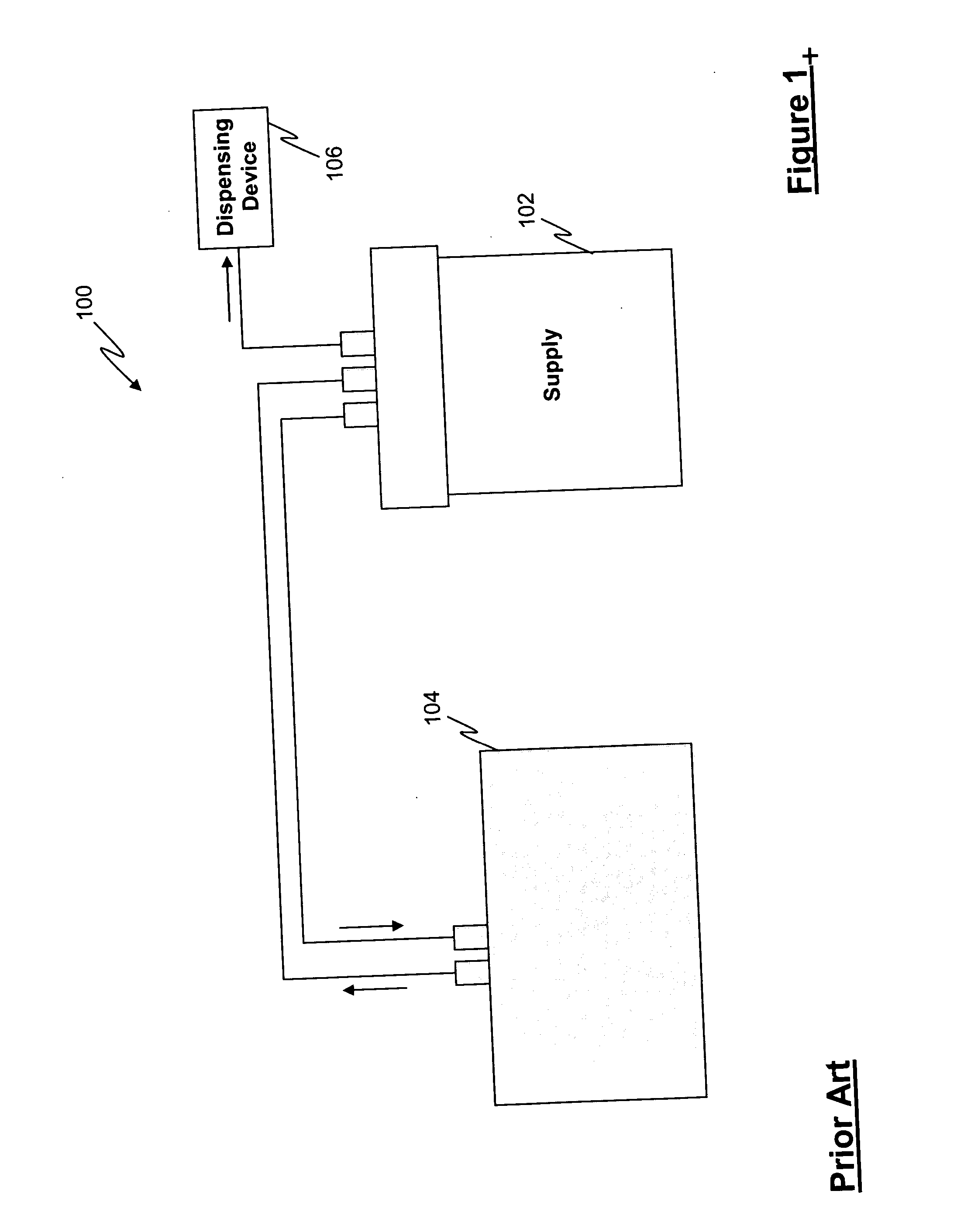
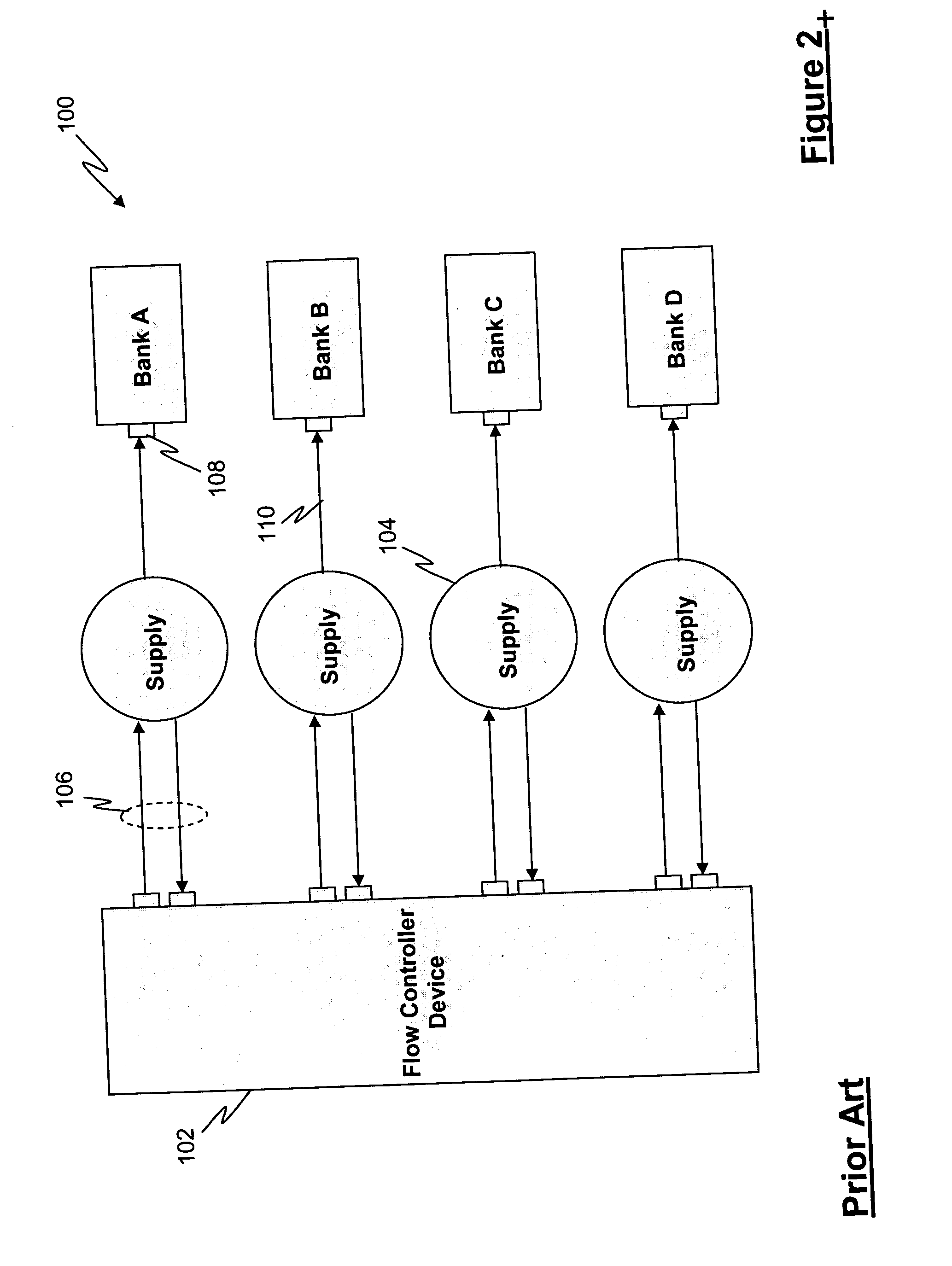
Unfortunately however, current fluid handling devices, such as the fluid handling device 100, include several disadvantages which involve limitations in its fluid handling capabilities.
For example, one disadvantage involves the dispensing of a fluid containing suspended matter.
When dispensing a fluid containing suspended matter, current fluid handling devices are unable to evenly and consistently dispense the fluid.
This lack of distribution control is undesirable because the uneven distribution of cells and / or beads can cause results from future processing to be skewed and inaccurate.
Another disadvantage involves the inability of current fluid handling devices to accurately and controllably dispense small volumes of fluids (and hence suspended matter) in several different formats.
As a result, approximately only 40% of assays are currently capable of being miniaturized on automated platforms.
This lack of miniaturization capability is undesirable because it requires that a majority of assays be processed by hand thus imposing a limitation on the number of assays that are capable of being processed in this manner using automation.

Method used


Image

  • Fluid handling device
  • Fluid handling device
  • Fluid handling device

Examples


Embodiment Construction

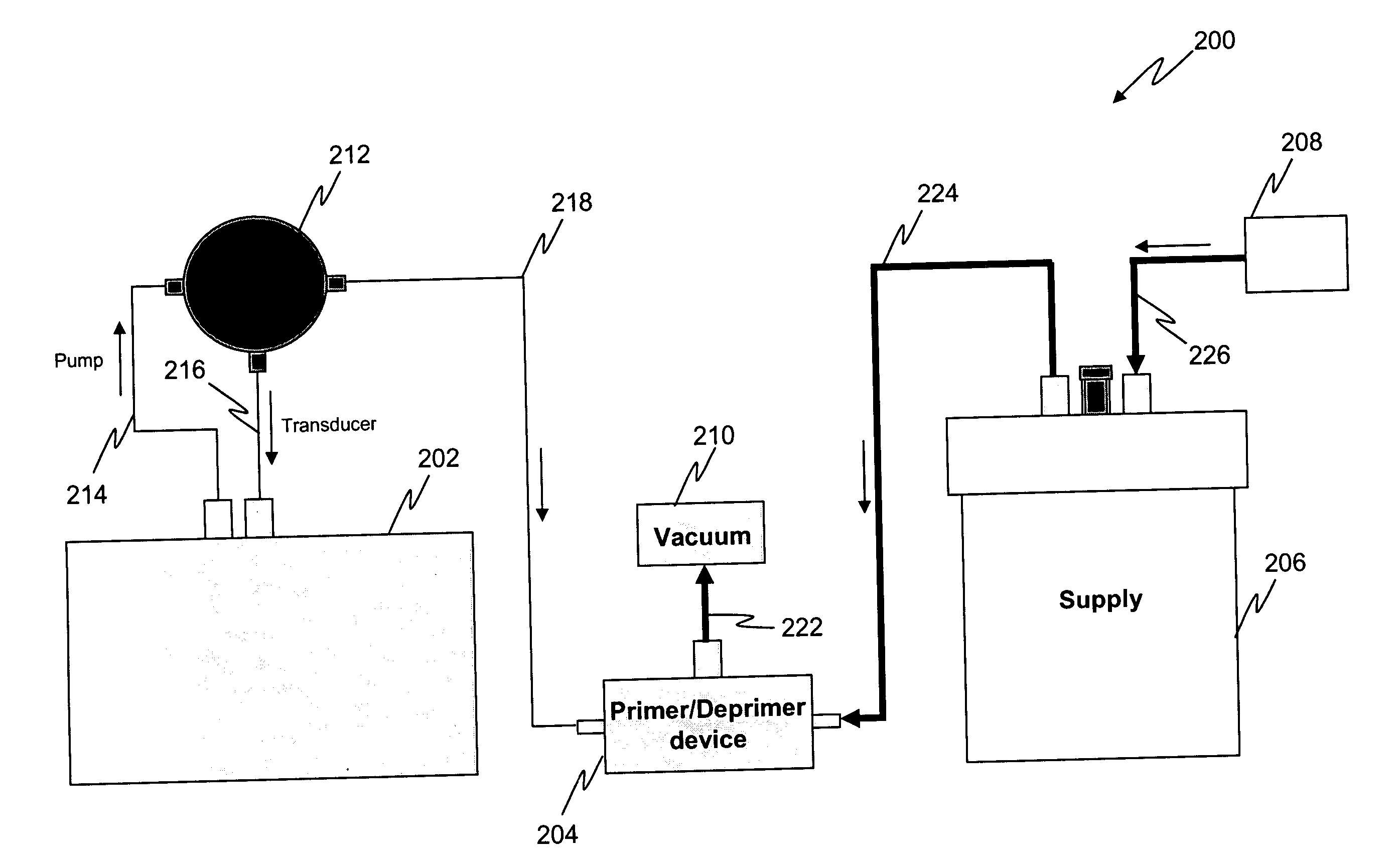
[0022] Referring to FIG. 3, a schematic block diagram illustrating one embodiment of a fluid handling device 200 in accordance with the present invention is shown and includes a pressure controller device 202, a primer / deprimer device or flow control device 204, a fluid container 206, a fluid transfer device 208 and a vacuum device 210 (which may be integrated with pressure controller device 202), wherein the pressure controller device 202 is in flow communication with the fluid container 206 via the flow control device 204. The at least one pressure controller device 202 is configured to be in flow communication with a valve 212 via a pressure tube 214 and a pressure monitoring device, such as transducer tube 216, wherein the valve 212 is in further flow communication with the flow control device 204 via a valve tube 218. The flow control device 204 is further communicated with the vacuum device 210 and the fluid container 206 via a vacuum tube 222 and a container flow tube 224, re...


PUM


Abstract

A fluid handling device and a method for implementing the fluid handling device is provided, wherein the fluid handling device includes a pressure control device configurable to generate at least one of a positive pressure and a negative pressure; and a flow control device having a flow control device output, wherein the flow control device is configurably associated with the pressure control device such that at least one of the positive pressure and the negative pressure is in flow communication with the flow control device output.

Description

CROSS-REFERENCE TO RELATED PATENT APPLICATIONS [0001] The present application is related to U.S. Provisional Patent Application No. 60 / 734,064 filed Nov. 07, 2005, the contents of which are incorporated by reference herein in their entirety.FIELD OF THE INVENTION [0002] This disclosure relates generally to the handling of an assay and more particularly to a multi-directional device for handling an assay. BACKGROUND OF THE INVENTION [0003] One of the main challenges for pharmaceutical companies in developing cures and treatments for illnesses involves controlling the costs required to develop and process the biological materials, such as proteins, enzymes and cell based assays, needed to create the desired drugs and medicines. Unfortunately however, many of the compounds included in drug screening assays are archival and only available in very limited quantities or they are the products of combinatorial synthesis procedures and thus are only produced in microgram to milligram quantit...

Claims


Application Information

Patent Timeline
IPC IPC(8): B67C3/16
CPCB01L3/0293B01L2200/0615B01L2200/146B01L2400/0487G01N35/1002G01N35/1016Y10T137/3109
Inventor BERNARD, CHRISTOPHER J.ZEWINSKI, JENNIFERO'CONNELL, JONATHAN C.
Owner BRISTOL MYERS SQUIBB CO
Learn More