Consolidation Joining of Thermoplastic Laminate Ducts

a technology of thermoplastic laminate and ducts, which is applied in the field of thermoplastic duct formation, can solve the problems of plaster that is typically removed or destroyed as waste, complex manufacturing process, and long manufacturing process of such reinforced thermoset ducts, and achieves good flammability, smoke and toxicity tests.

Active Publication Date: 2007-05-17
THE BOEING CO
View PDF28 Cites 13 Cited by
  • Summary
  • Abstract
  • Description
  • Claims
  • Application Information

AI Technical Summary

Benefits of technology

[0014] The present invention provides an apparatus and method for forming thermoplastic ducts with consolidation joints. The ducts can be formed of preforms, which can be thermoplastic laminate sheets preformed to a bent configuration. The thermoplastic material is lightweight, strong, and performs well in flammability, smoke, and toxicity tests. Further, the disposable plaster mandrels for supporting plies are not required, nor are duct-specific rotatable tools for forming such mandrels. Additionally, consolidation joints achieved by the apparatus and method can be strong, and the method is adaptable for automated operation.
[0018] According to yet another aspect of the present invention, the second support structure includes the elastomeric device, which is configured to receive a fluid for inflation. The elastomeric device can be inflated to fill the cavity and exert a radially outward pressure, for example, of at least about 20 psi on the preform. The first support structure can include a hollow tube that extends from a first end to a second end and defines a cylindrical cavity therein. The tube can define a slit that extends longitudinally between the ends so that the tube can be adjusted between a closed position and an open position, and the diameter of the tube is reduced by closing the tube.

Problems solved by technology

However, the manufacturing process can be complicated, lengthy, and expensive, especially for specially shaped ducts such as curved ducts and ducts that include a spud or attached fitting, a bead, a bell or flared portion, a conical section, or another contour.
The manufacturing process for such reinforced thermoset ducts is complicated, time consuming, and expensive.
The plaster mandrel is formed and destroyed during the manufacture of one duct, requiring time for curing and resulting in plaster that typically must be removed or destroyed as waste.
Like the rotatable tools used for forming the mandrels, the jigs require time and expense for manufacture, storage, and maintenance.
Additionally, ducts formed of common thermoset epoxies do not perform well in certain flammability, smoke, and toxicity tests, and the use of such materials can be unacceptable if performance requirements are strict.
Methods for joining members formed from thermoplastic composites are known in the art, but none of the known methods are ideal.
Undesirably, composites that contain fiber reinforcements, especially long or continuous fibers, can be damaged by these frictional heating methods.
Locating tools and backing members for supporting the members are often required, and large members can be difficult to reciprocate.
Additionally, ultrasonic methods typically require surface preparations, and friction stirring is typically slow.
Hot plate joining generally requires simple tooling but is time consuming and is not practical for use with complex shapes.
Further, the hot plate can introduce contamination into the interface of the members or oxidize the composite materials, thereby weakening the joint.
Hot gas and extrusion joining are typically slow, and the quality of the resulting joint can vary significantly depending on the skill of the operator.
The heating element, which remains in the joint, increases the cost of the joining method and affects the characteristics of the joint, for example, making the joint stiffer than the other portions of the members.
Typically, the heating element has a different coefficient of thermal expansion than the thermoplastic material, resulting in stresses in the joint when heated or cooled.
The powder adds to the cost of the joint, and the method is generally limited to joining members of limited thickness.
Infrared joining, i.e., using an infrared lamp to heat the interface and then pressing the members together, requires a complicated set up and can be time consuming, depending on the absorption characteristics of the members.

Method used


Image

  • Consolidation Joining of Thermoplastic Laminate Ducts
  • Consolidation Joining of Thermoplastic Laminate Ducts
  • Consolidation Joining of Thermoplastic Laminate Ducts

Examples


Embodiment Construction

[0032] The present invention now will be described more fully hereinafter with reference to the accompanying drawings, in which preferred embodiments of the invention are shown. This invention may, however, be embodied in many different forms and should not be construed as limited to the embodiments set forth herein; rather, these embodiments are provided so that this disclosure will be thorough and complete, and will fully convey the scope of the invention to those skilled in the art. Like numbers refer to like elements throughout.

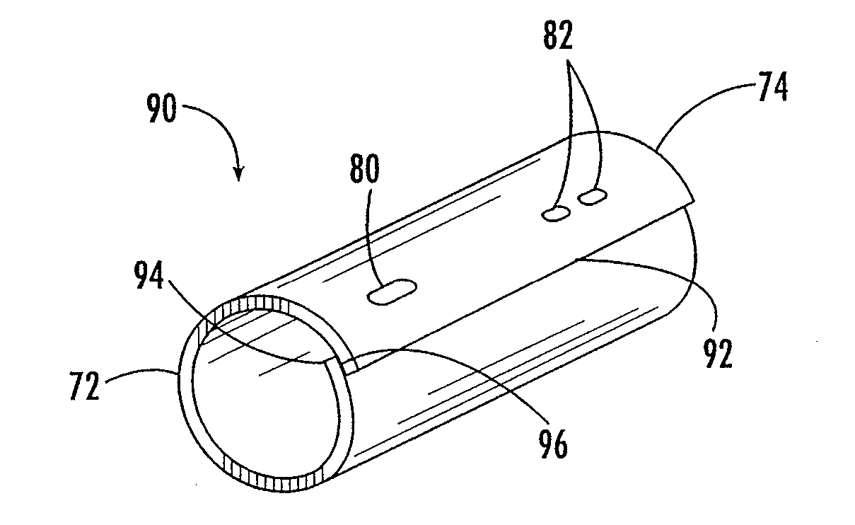
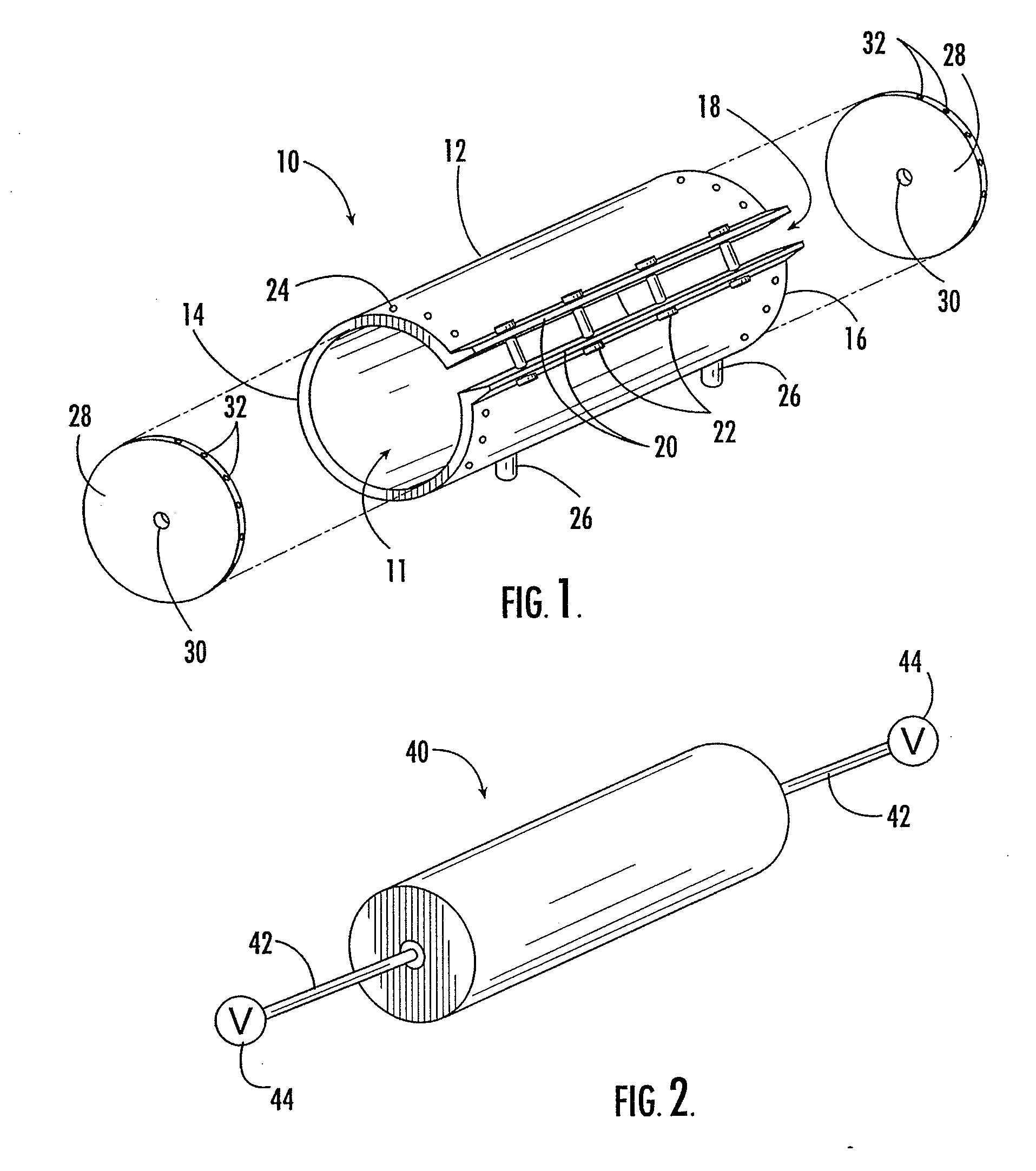
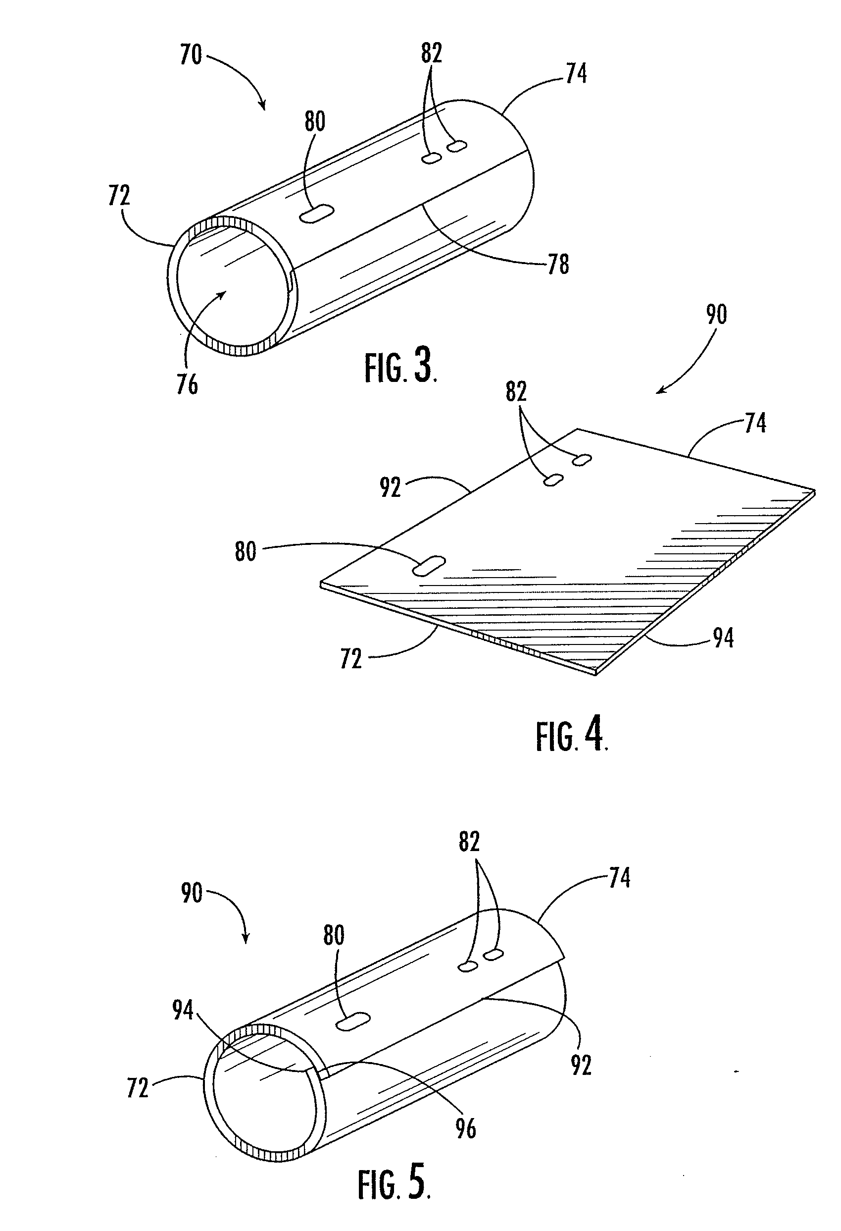
[0033] Referring now to FIG. 1, there is shown a consolidation joiner 10 for forming consolidation joints in thermoplastic members according to one embodiment of the present invention. The consolidation joiner 10 includes an outer support structure comprised of a tube or elongate cylinder 12 that extends longitudinally from a first end 14 to a second end 16 and defines a continuous cavity 11 therethrough. In this embodiment, the elongate cylinder 12 defi...


PUM

PropertyMeasurementUnit
pressureaaaaaaaaaa
diameteraaaaaaaaaa
diameteraaaaaaaaaa

Abstract

There is provided an apparatus and method for consolidation joining a thermoplastic preform to form a duct. The apparatus includes first and second longitudinally extending support structures. The first support structure at least partially defines a cavity for supporting the preform in a desired configuration of the duct. The second support structure extends in the cavity such that the preform can be supported between the first and second support structures. The second support structures can include an elastomeric device that is configured to adjust radially and urge the interface of the preform against the first support structure. A heater is configured to heat an interface of the preform to above a glass transition temperature. The resulting duct is has a longitudinal consolidation joint and defines a passage.

Description

CROSS REFERENCE TO RELATED APPLICATIONS [0001] This application is a divisional of U.S. patent application Ser. No. 10 / 215,833, filed Aug. 9, 2002, which is hereby incorporated herein in its entirety by reference.BACKGROUND OF THE INVENTION [0002] 1) Field of the Invention [0003] The present invention relates to apparatuses and methods for forming ducts and, more specifically, thermoplastic ducts formed by consolidation joining. [0004] 2) Description of Related Art [0005] Ducts provide transport passageways for a wide variety of applications. For example, tubular ducts are widely used for air flow in aircraft environmental control systems. Similarly, ducts provide passageways for transporting gases for heating and ventilation in other vehicles and in buildings. Water distribution systems, hydraulic systems, and other fluid networks also often use ducts for fluid transport. In addition, solid materials, for example, in particulate form can be delivered through ducts. Ducts for the fo...

Claims


Application Information

Patent Timeline
Patent Type & Authority Applications(United States)
IPC IPC(8): B32B37/00B29C35/02B29C43/36B29C53/42B29C65/00
CPCB29C35/0233Y10T156/1036B29C53/42B29C66/81455B29C66/91943B29C2043/3644B29K2079/085B29K2081/04B29L2023/22B29C66/91221B29C66/91411B29C66/91431B29C66/961B29C66/91445B29C66/919B29C66/91945Y10T156/1013Y10T156/1038B29C43/3642B29C65/02B29C65/06B29C65/08B29C65/10B29C65/14B29C65/1425B29C65/16B29C65/20B29C66/0044B29C66/71B29C66/7212B29C66/7392B29C66/8122B29C66/81821B29K2307/04B29K2309/08B29K2277/10B29K2827/18B29K2077/10
Inventor FRANTZ, WALTER FORRESTLUM, MATTHEW K.YOUNIE, MARK L.
Owner THE BOEING CO
Why Eureka
Try Eureka