Motor for a fuel pump

a fuel pump and electric commutation technology, applied in the direction of piston pumps, magnetic circuit rotating parts, magnetic circuit shapes/forms/construction, etc., can solve the problem of permanent damage of the rotor, and achieve high chemical resistance, high deformation resistance, and high dimensional stability

Inactive Publication Date: 2007-05-17
CONTINENTAL AUTOMOTIVE GMBH
View PDF31 Cites 6 Cited by
  • Summary
  • Abstract
  • Description
  • Claims
  • Application Information

AI Technical Summary

Benefits of technology

[0014] In principle, any desired fuel-resistant plastics which have high deformation resistance can be used as a support for the ferrite. However, polyphenylene sulfide (PPS) is a particularly advantageous plastic which bonds the ferrite, especially for providing the shaped body with a high degree of chemical resistance and very high dimensional stability. A further advantage of PPS is its inherent flame resistance. Since the ferrite is responsible for the permanent-magnet properties of the rotor, it is also expedient if it has a high coercive force.
[0015] According to one advantageous development of the invention which was discovered from experiments, the shaped body has stabilizing fiber material. A proportion by volume of approximately 2% of glass fibers has proven particularly suitable and also cost-effective.
[0016] It is possible to imagine placing the shaped body, for example, onto the shaft and adhesively bonding them. In contrast, a particularly simple and long-lasting connection between the rotor and the shaft while at the same time avoiding an unbalance of the rotor is ensured when, according to another advantageous development of the invention, the shaped body is injection molded onto the shaft and, in a connecting region between the shaft and the shaped body, the shaft has a pattern which increases its surface roughness. This pattern may be, for example, a roughened section or—particularly advantageously—a knurled formation.
[0017] The motor can be produced in a particularly simple and cost-effective manner when, according to another advantageous development of the invention, the return element is pressed onto the shaft. In this case, the return element can be pressed onto the shaft, after the shaped body and shaft are connected, so as to ensure exact adjustment in relation to the shaped body.

Problems solved by technology

One problem with the known motors is that the rotor is permanently damaged when it comes into contact with gasoline or diesel fuel, as is unavoidable when the motors are used to drive fuel pumps.

Method used


Image

  • Motor for a fuel pump
  • Motor for a fuel pump

Examples


Embodiment Construction

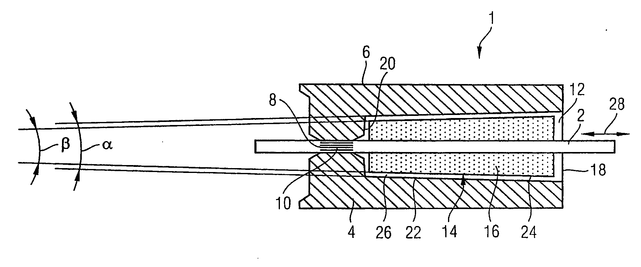
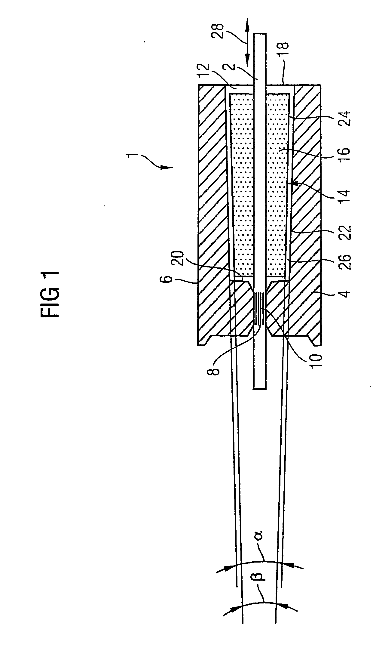
[0019] The figure is a schematic view of a rotor 1 of an electronically commutated motor (not illustrated in any more detail) for a fuel pump, said rotor having two or more magnetic poles. The rotor 1 is connected to a shaft 2 in a rotationally fixed manner and has a plastic-bonded ferrite 4 which is admixed with a stabilizing fiber material. The plastic-bonded ferrite 4 forms a fuel-resistant shaped body 6 which is injection molded onto the shaft 2 and at the same time is magnetized, so that it forms a multipole permanent magnet. In a connecting region 8 between the shaft 2 and the shaped body 6, the shaft 2 has a pattern 10 which increases its surface roughness and is in the form of a knurl.

[0020] The shaped body 6 also has an axial recess 12 in which a return element 14 which is composed of a soft-magnetic material 16 engages. The return element 14 increases the magnetic flux and, in accordance with requirements, may be dimensioned as a function of the shaped body 6 and the moto...


PUM


Abstract

An electrically commutated motor for a fuel pump having a rotor connected to a shaft and having plastic-bonded ferrite, with a fuel-resistant shaped body formed by the plastic-bonded ferrite, and a magnetic return element adjustable in relation to the shaped body.

Description

FIELD OF THE INVENTION [0001] The invention relates to an electronically commutated motor for a fuel pump, comprising a rotor which is connected to a shaft in a rotationally fixed manner and has a plastic-bonded ferrite. DISCUSSION OF THE PRIOR ART [0002] Electronically commutated motors in the form of commutatorless DC motors, so called electronic motors, are known. Such brushless DC motors are distinguished in that they do not require servicing and the cost of producing them is comparatively low. It is also known to provide such motors with a rotor which is arranged on a shaft and is composed of a permanent-magnet material, for example a plastic-bonded barium ferrite. [0003] One problem with the known motors is that the rotor is permanently damaged when it comes into contact with gasoline or diesel fuel, as is unavoidable when the motors are used to drive fuel pumps. Furthermore, the motors have a large spectrum of efficiency which is dependent on further system parameters. [0004]...

Claims


Application Information

Patent Timeline
Patent Type & Authority Applications(United States)
IPC IPC(8): H02K1/04H02K15/12H02K21/12F02M37/08H02K1/02H02K1/27H02K5/12H02K21/00
CPCF02M37/08H02K21/027H02K5/12H02K1/2733H02K1/02H02K1/27
Inventor BAEMPFER, MICHAELMISSUN, JENSWARNKE, WOLFGANG
Owner CONTINENTAL AUTOMOTIVE GMBH
Why Eureka
Try Eureka