Energy absorption device

An energy-absorbing device and energy-absorbing technology, applied in the direction of elastic shock absorbers, springs/shock absorbers, shock absorbers, etc., can solve problems such as the longitudinal effect of tilted vehicles

Inactive Publication Date: 2012-03-21
COSMA ENG EURO AG
View PDF7 Cites 0 Cited by
  • Summary
  • Abstract
  • Description
  • Claims
  • Application Information

AI Technical Summary

Problems solved by technology

[0004] However, in practice, there may be accident forces acting obliquely to the longitudinal direction of the vehicle

Method used


Image

  • Energy absorption device
  • Energy absorption device
  • Energy absorption device

Examples


Embodiment Construction

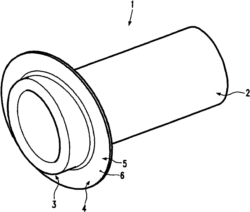
[0046] figure 1 The energy-absorbing device 1 according to the first embodiment of the invention is shown in a perspective view. The energy-absorbing device has a hollow longitudinal section 2 designated for deformation. A rolled-up region 3 adjoins the hollow longitudinal section 2 , on which a fastening section 4 is arranged as an extension. This fastening section defines the fastening plane of the energy-absorbing device 1 .

[0047] In this embodiment of the invention, the fastening section 4 is substantially flange-shaped, and the fastening plane 5 is defined by the abutment surface 6 of the fastening section 4 on the side of the roll-up region 3 .

[0048] The fixing section can also be designed as a brim shape or a flange shape.

[0049] The hollow longitudinal section 2 is tubular in this embodiment of the invention. However, other open or closed hollow bodies, for example with polygonal cross-sections, can also be used.

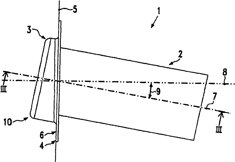
[0050] exist figure 2 The energy-absorb...


PUM


Abstract

The present invention relates to an energy absorption device (1) for a bumper arrangement of a vehicle, with a hollow longitudinal section (2) intended for deformation, a rolled-back region (3) adjoining the hollow longitudinal section, and an extension section (4) connected to the rolled-back region. In order to improve an energy absorption device of this type to the extent that obliquely actingaccident forces can be absorbed with a high degree of efficiency in as simple a manner as possible, it is proposed, in an initial state prior to energy absorption, to orient the hollow longitudinal section (2) obliquely with respect to the axial direction of the extension section (4).

Description

technical field [0001] The invention relates to an energy absorbing device having a first hollow longitudinal section of a first cross-sectional dimension (cross-sectional width) and a second hollow longitudinal section of a second cross-sectional dimension, and a Rollover transition area. Background technique [0002] Such energy-absorbing devices are used in vehicles and are arranged, for example, on shock absorbers and between the body. In the event of an accident, the energy-absorbing device is plastically deformed and thus absorbs energy. In the event of a minor accident, the energy-absorbing capacity is sufficient to prevent plastic deformation of the body. [0003] In order to ensure trouble-free deformation, ie to collapse together, the energy-absorbing device is arranged to be oriented parallel to the longitudinal direction of the vehicle. [0004] In practice, however, accident forces acting obliquely to the longitudinal direction of the vehicle may occur. In...

Claims


Application Information

Patent Timeline
Patent Type & Authority Patents(China)
IPC IPC(8): B60R19/34F16F7/12
CPCF16F7/123B60R19/34
Inventor 托罗斯·阿克金迈克尔·布吕梅尔
Owner COSMA ENG EURO AG
Why Eureka
Try Eureka