
Remote device management in a home automation data transfer system

a technology of remote device management and data transfer system, which is applied in the field of remote device management in the home automation network, can solve the problems of large bandwidth, difficult upgrade of network and application software in the field, and large amount of time spent training developers

Inactive Publication Date: 2007-05-17
INTERMATIC
View PDF29 Cites 158 Cited by
  • Summary
  • Abstract
  • Description
  • Claims
  • Application Information

AI Technical Summary

Problems solved by technology

A large amount of time may be spent in training these developers on the underlying protocol and on these repetitive tasks.
Once the PC is removed from the system, network and application software become difficult to upgrade in the field.
Further, home automation networks have, in the past, been designed from and engineering point of view and may require large bandwidth to operate.
The user interface and system understanding may require a large amount of technical background.
Existing software development platforms may not be portable to multiple network protocols.
Porting the applications may not be possible if the network were expanded across different protocols.

Method used


Image

  • Remote device management in a home automation data transfer system
  • Remote device management in a home automation data transfer system
  • Remote device management in a home automation data transfer system

Examples


Embodiment Construction

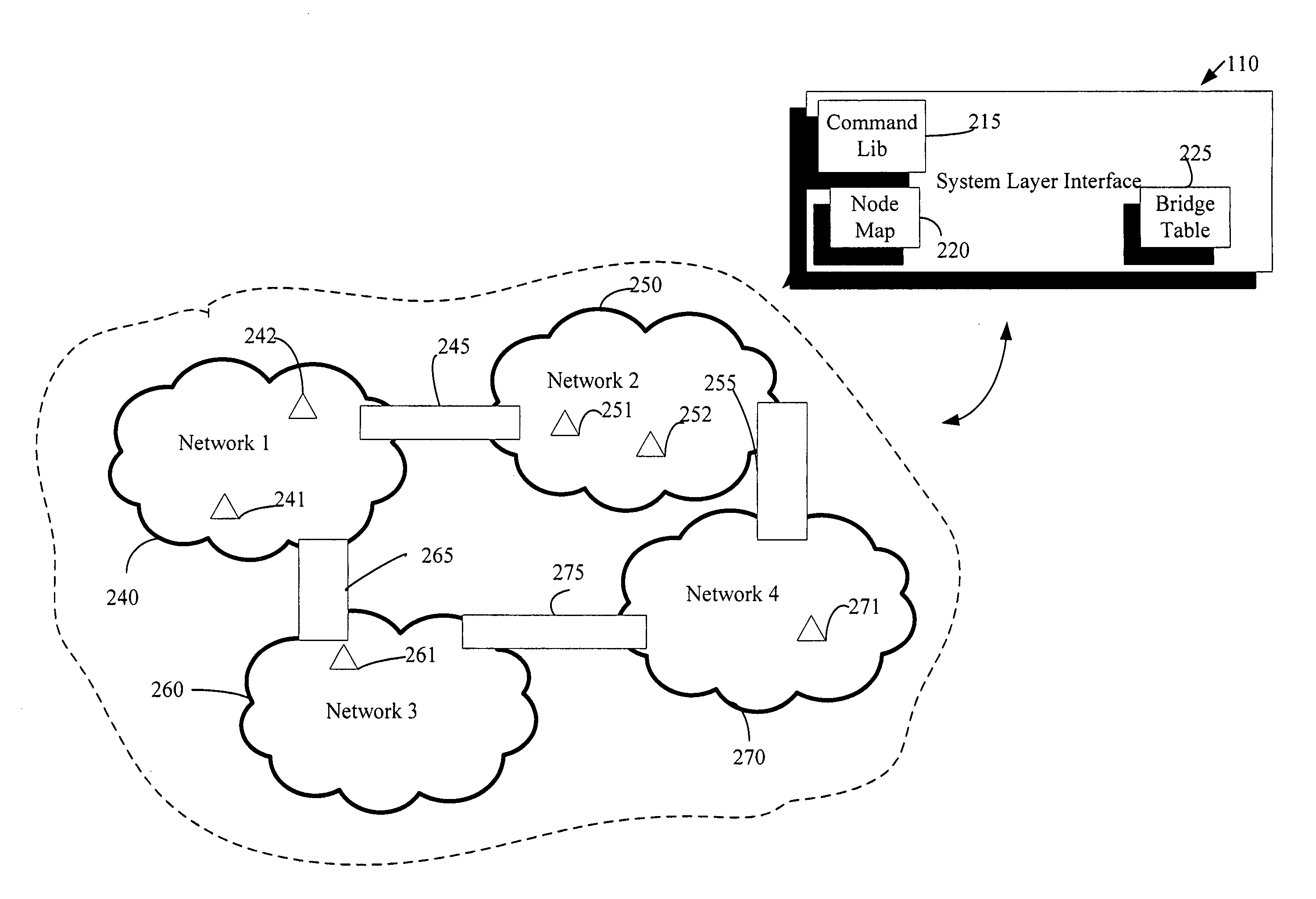
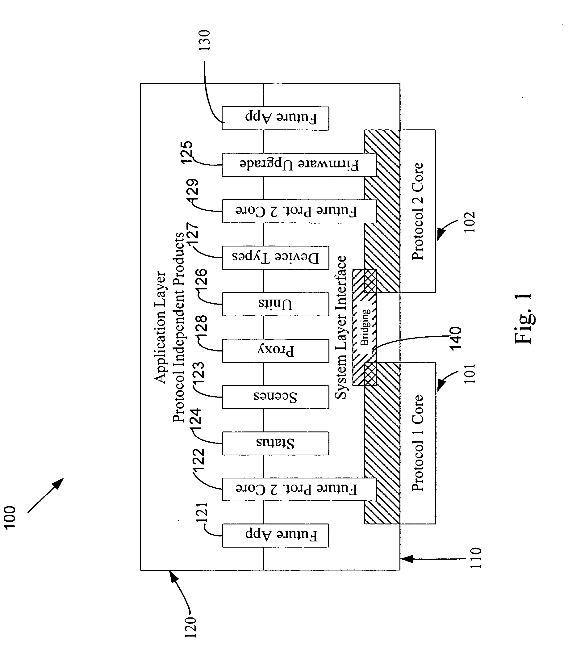
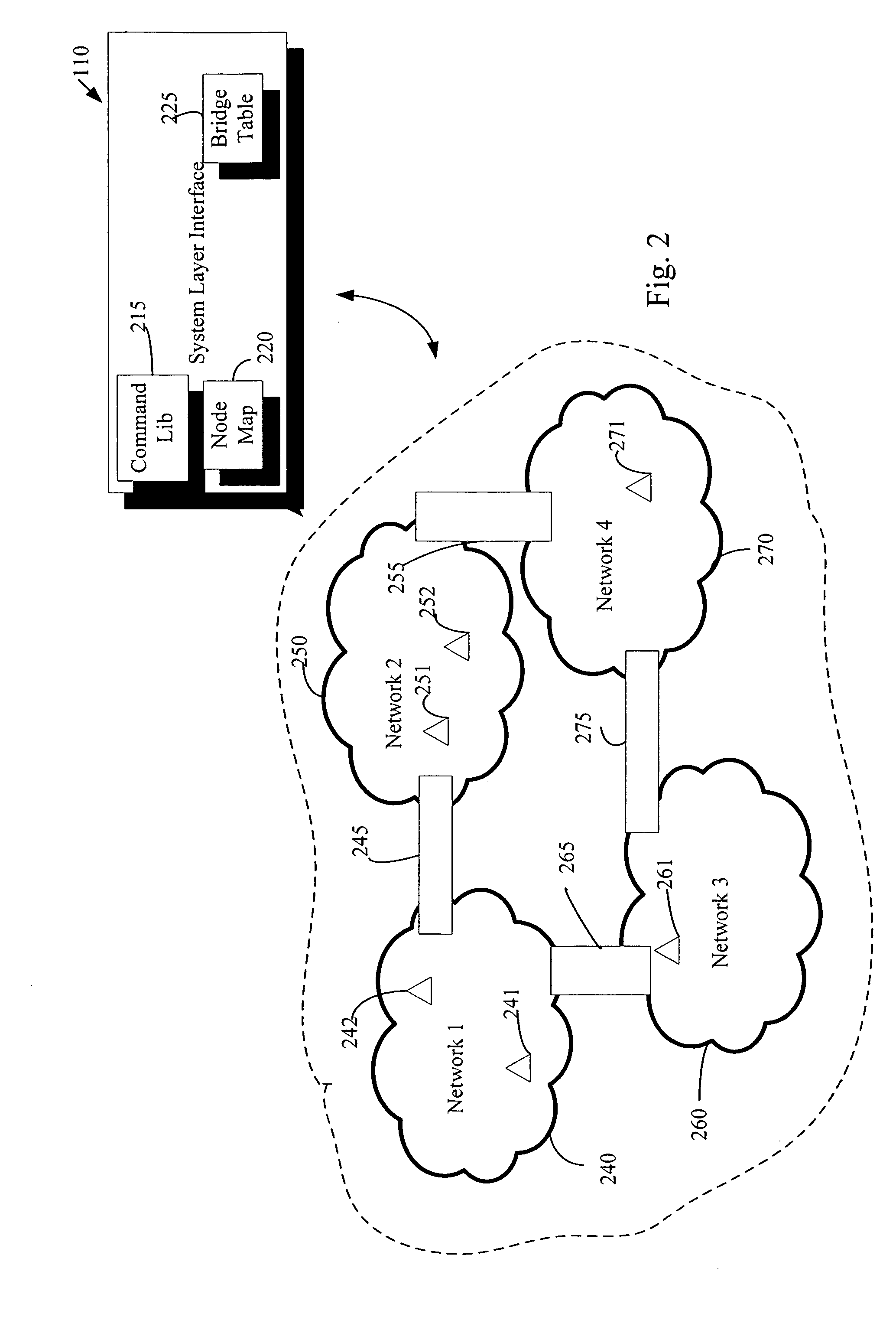
[0025]FIG. 1 illustrates a network abstraction block diagram 100. A network transport layer, such as a first protocol network core 101 or a second protocol network core 102 may reside at the lowest level of the network layers. The network transport layer 101 may include hardware and / or software for implementing network transport functions for the network. The first protocol network core 101 and / or the second protocol network core 102 may provide transparent transfer of data between end users, relieving the upper layers from any concern with providing reliable and cost-effective data transfer. The transport layer controls the reliability of a given link. Some transport protocols may be connection oriented, where the transport layer may track packets and retransmit those that fail. The first protocol network core 101 and / or the second protocol network core 102 may implement protocols such as the Z-Wave® home automation transport protocol. Other network protocols, such as commercial, i...


PUM


Abstract

An automation network includes automation network devices connected to the network and a system layer interface that interfaces with a transport layer and an application layer of the home automation network. The system layer interface includes command libraries configured to upgrade a remote network device. The automation network queries the network devices to determine if there are lost network devices or newly added network devices. The automation network may update a new remote device with scene information related to any lost network devices.

Description

PRIORITY CLAIM [0001] The present application claims the benefit of priority of U.S. Provisional Application Ser. No. 60 / 733,514, “Data Transfer System,” filed Nov. 4, 2005, the contents of which are incorporated by reference in their entirety herein. RELATED APPLICATIONS [0002] This application is related to U.S. patent application Ser. No. ______, “Device Types and Units for a Home Automation Data Transfer System,” (Atty. Docket No. 1390.947); U.S. patent application Ser. No. ______, “Proxy Commands and Devices for a Home Automation Data Transfer System,” (Atty. Docket No. 1390.948); U.S. patent application Ser. No. ______, “Application Updating in a Home Automation Data Transfer System,” (Atty. Docket No. 1390.949); and U.S. patent application Ser. No. ______, “Messaging in a Home Automation Data Transfer System,” (Atty. Docket No. 1390.950); and U.S. patent application Ser. No. ______, “Protocol Independent Application Layer for an Automation Network,” (Atty. Docket No. 1390.952...

Claims


Application Information

Patent Timeline
IPC IPC(8): H04L12/28H04L12/56
CPCH04L12/24H04L12/2803H04L12/2814H04L41/00H04L41/22
Inventor RECKAMP, STEVEN R.DINESCU, MIKYMAZZA, JOSEPHAPER, GREGORY J.PELLAND, MICHAELDOORHY, BRENDANGAZA, BRIANBOVEE, JEFFREY K.DUITSMAN, TIM
Owner INTERMATIC
Learn More