Power system for ultraviolet lighting

a power system and ultraviolet light technology, applied in the field of power systems, can solve the problems of no known alternative electric lights that may be employed, severe abdominal cramps and diarrhea, and the ineffectiveness of the ozonation system and the membrane system,

Inactive Publication Date: 2007-05-17
SHIPP DAVID D +4
View PDF10 Cites 4 Cited by
  • Summary
  • Abstract
  • Description
  • Claims
  • Application Information

AI Technical Summary

Benefits of technology

[0029] As another aspect of the invention, a low voltage power system for ultraviolet lighting comprises: a first normally closed circuit interrupter structured to receive a low voltage power source and output a first output responsive to predetermined voltage and forward power flow conditions; a second normally closed circuit interrupter structured to receive a low voltage power source and output a second ou...

Problems solved by technology

Drinking water with these parasites, when ingested, can cause severe abdominal cramps and diarrhea.
However, an ozonation system is not as effective as a UV system or a membrane system.
Other than UV lights, there are no known alternative electric lights that may be employed to inactivate Cr...

Method used


Image

  • Power system for ultraviolet lighting
  • Power system for ultraviolet lighting
  • Power system for ultraviolet lighting

Examples


example 1

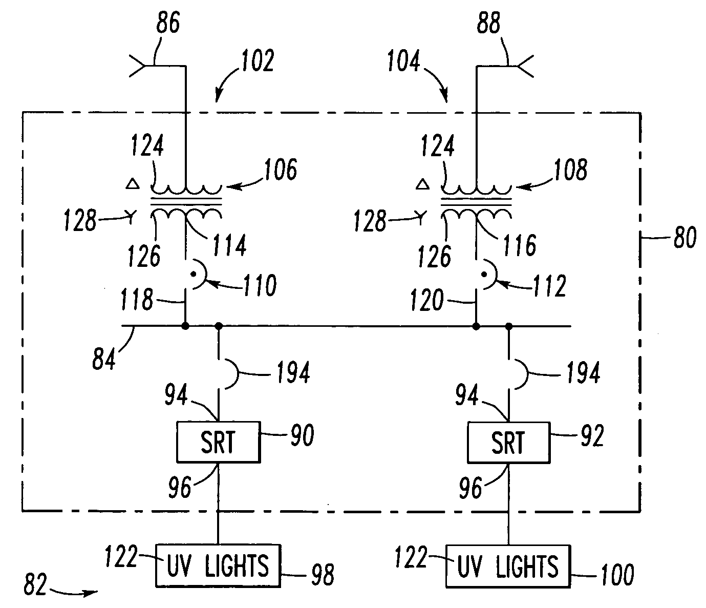
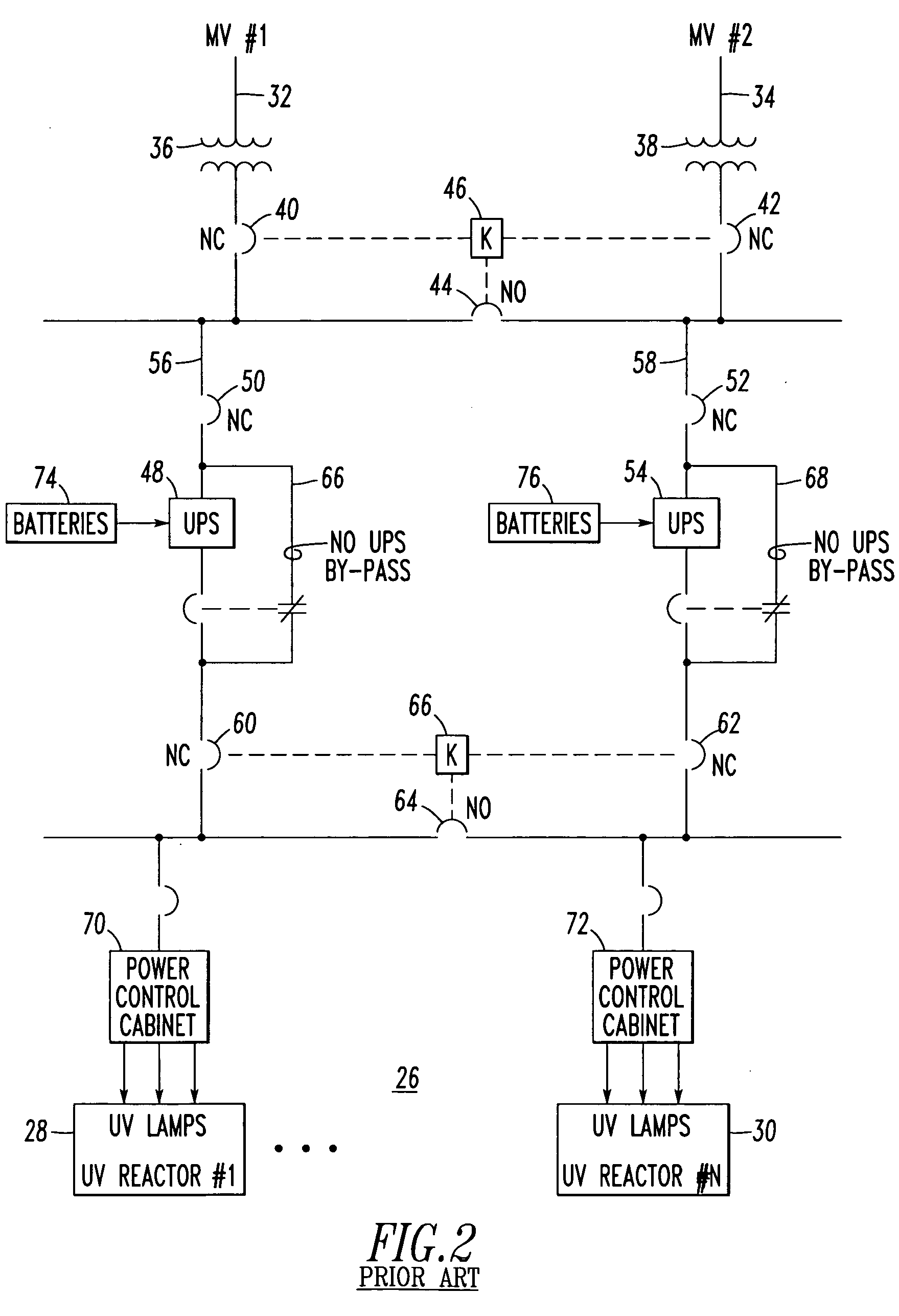
[0038] In this example, the spot network 84 powers two SRT devices 90,92, although three of more SRT devices may be employed. Also, the spot network 84 is powered from two feeder systems 102,104, although three or more feeder systems may be employed. Each of the example feeder systems 102,104 includes a network transformer, 106 or 108, and a network protector, 110 or 112. The first network transformer 106 is structured to be powered from the first MV feeder 86 and to output a first output 114. The second network transformer 108 is structured to be powered from the second MV feeder 88 and to output a second output 116. The first network protector 110 inputs the first output 114 of the first network transformer 106 and outputs a third output 118. The second network protector 112 inputs the second output 116 of the second network transformer 108 and outputs a fourth output 120. In turn, the spot network 84 is powered from the third and fourth outputs 118,120, and powers the example SRT...

example 2

[0039] The power sources, such as the example MV feeders 86,88, are MV power sources, and the first and second outputs 114,116 are low voltage outputs. In turn, the UV lights 98,100 are powered from a suitable low voltage (e.g., without limitation, less than about 1 kVAC; about 480 VAC (US); about 380 VAC (Europe); about 600 VAC (Canada); any suitable low voltage). The inputs to the UV lights 98,100 are transformed to a relatively higher voltage through a suitable type of ballast transformer / electronics (not shown) with the actual individual UV lamps 122 being powered at a relatively much higher voltage (e.g., a suitable voltage determined by the manufacturer of the UV lights 98,100).

example 3

[0040] As employed herein, the term “network” refers to a low voltage power system including a plurality of power sources wherein the design criterion is to maintain network power with a relatively very high reliability. For example, a typical network includes about four to about eight (not shown) interconnected transformer sources. Each transformer source includes a network protector, such as 110 or 112, which does not trip into the forward direction (in which power flows through the transformer to the network load), but which does trip relatively very quickly if reverse power flows from the network load to the transformer. A “spot network,” such as 84, is a relatively smaller network in which there are about two or about three or more transformers connected to a common bus. A typical application is a utility vault (not shown) on a floor of a high-rise building (not shown) or in a water treatment room (not shown). In contrast, a full network has its transformers remotely located fr...


PUM


Abstract

A power system for ultraviolet lighting includes a first network transformer structured to be powered from a first medium voltage power source and to output a first low voltage output; and a second network transformer structured to be powered from a second medium voltage power source and to output a second low voltage output. A first network protector inputs the first low voltage output of the first network transformer and outputs a third output. A second network protector inputs the second low voltage output of the second network transformer and outputs a fourth output. A spot network is powered from the third output of the first network protector and from the fourth output of the second network protector. A number of sag ride thru devices include an input powered from the spot network and an output structured to power a number of ultraviolet lights.

Description

BACKGROUND OF THE INVENTION [0001] 1. Field of the Invention [0002] This invention pertains generally to power systems and, more particularly, to power systems for ultraviolet lighting. [0003] 2. Background Information [0004] Ultraviolet (UV) lights are effective and reliable barriers against, for example, Cryptosporidium and Giardia, which are present in almost all surface waters. These microscopic parasites are resistant to traditional water treatment methods, such as chlorination. Drinking water with these parasites, when ingested, can cause severe abdominal cramps and diarrhea. [0005] The cost, for example, of a medium pressure (i.e., with respect to untreated water) UV system for inactivation of Cryptosporidium and Giardia is about $0.05 per 1000 gallons of untreated water as compared to about $0.75 per 1000 gallons for a membrane system and about $0.20 per 1000 gallons for an ozonation system. However, an ozonation system is not as effective as a UV system or a membrane system...

Claims


Application Information

Patent Timeline
IPC IPC(8): H01S3/13
CPCH02H3/003H05B41/245H05B41/2853
Inventor SHIPP, DAVID D.PIETRYKA, RICHARD S.CARNOVALE, DANIEL J.SHAH, KANAIYALAL R.KOCIOLEK, MICHAEL J. SR.
Owner SHIPP DAVID D
Why Eureka
Try Eureka