Air vent register

Inactive Publication Date: 2007-05-17
HOWA PLASTICS CO LTD
View PDF4 Cites 74 Cited by
  • Summary
  • Abstract
  • Description
  • Claims
  • Application Information

AI Technical Summary

Benefits of technology

[0018] When swung or slid along the fin, the projection of the rubber-like elastic element disposed inside the knob body slides while pressing the fin. This arrangement will cause an adequate sliding resistance between the fin and elastic element, so that the knob will be manipulated with a favorable operating load.
[0019] Moreover, if there is a variation from product to prod

Problems solved by technology

However, this arrangement complicates the structure of the operation knob and also increases the number of parts.
In addition, since the arms and spring member are exposed at the rear side of the knob body, they become visible from the front side of the register when the knob is manipulated downward, thereby adversely affecting the appearance of the register.
However, although this operation knob of the above register

Method used


Image

  • Air vent register
  • Air vent register
  • Air vent register

Examples


Embodiment Construction

[0028] Preferred embodiments of the present invention are now described below with reference to the accompanying drawings. However, the invention is not limited to the embodiments disclosedherein. Allmodifications within the appended claims and equivalents relative thereto are intended to be encompassed in the scope of the claims.

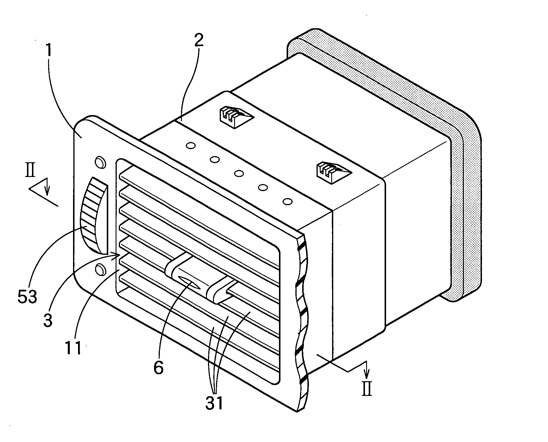
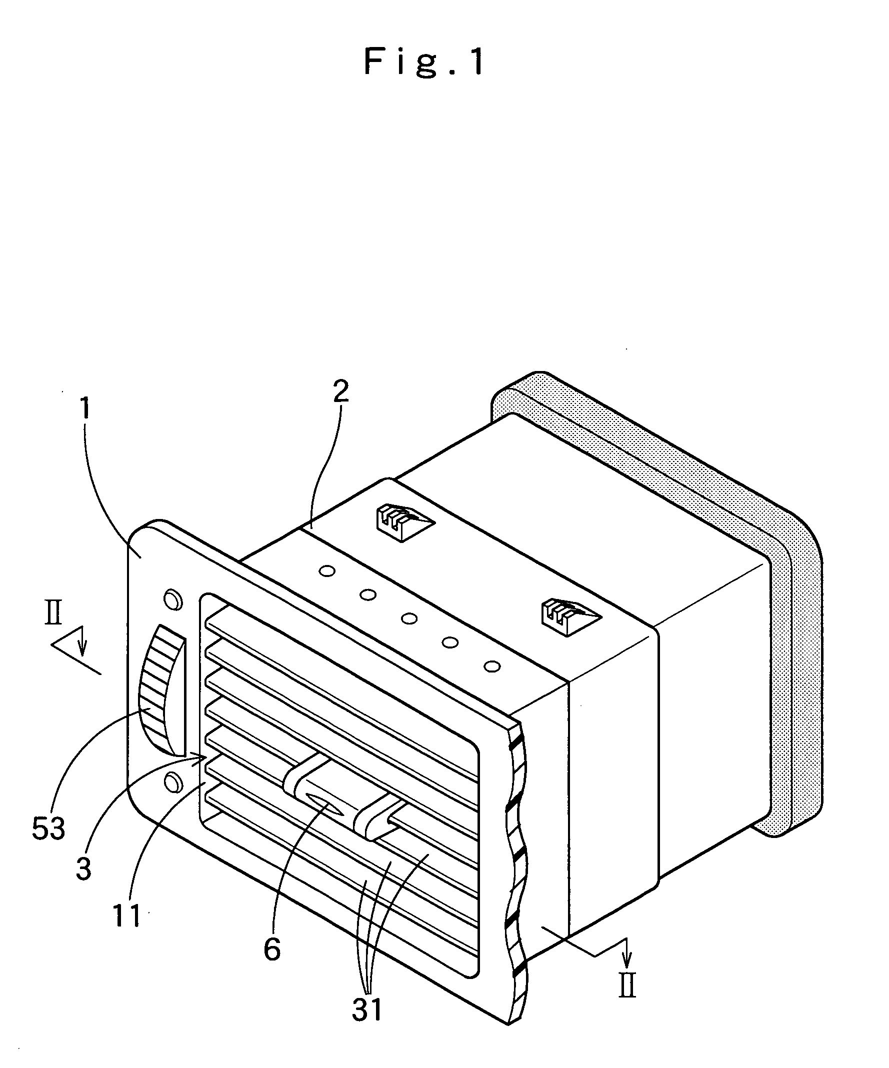
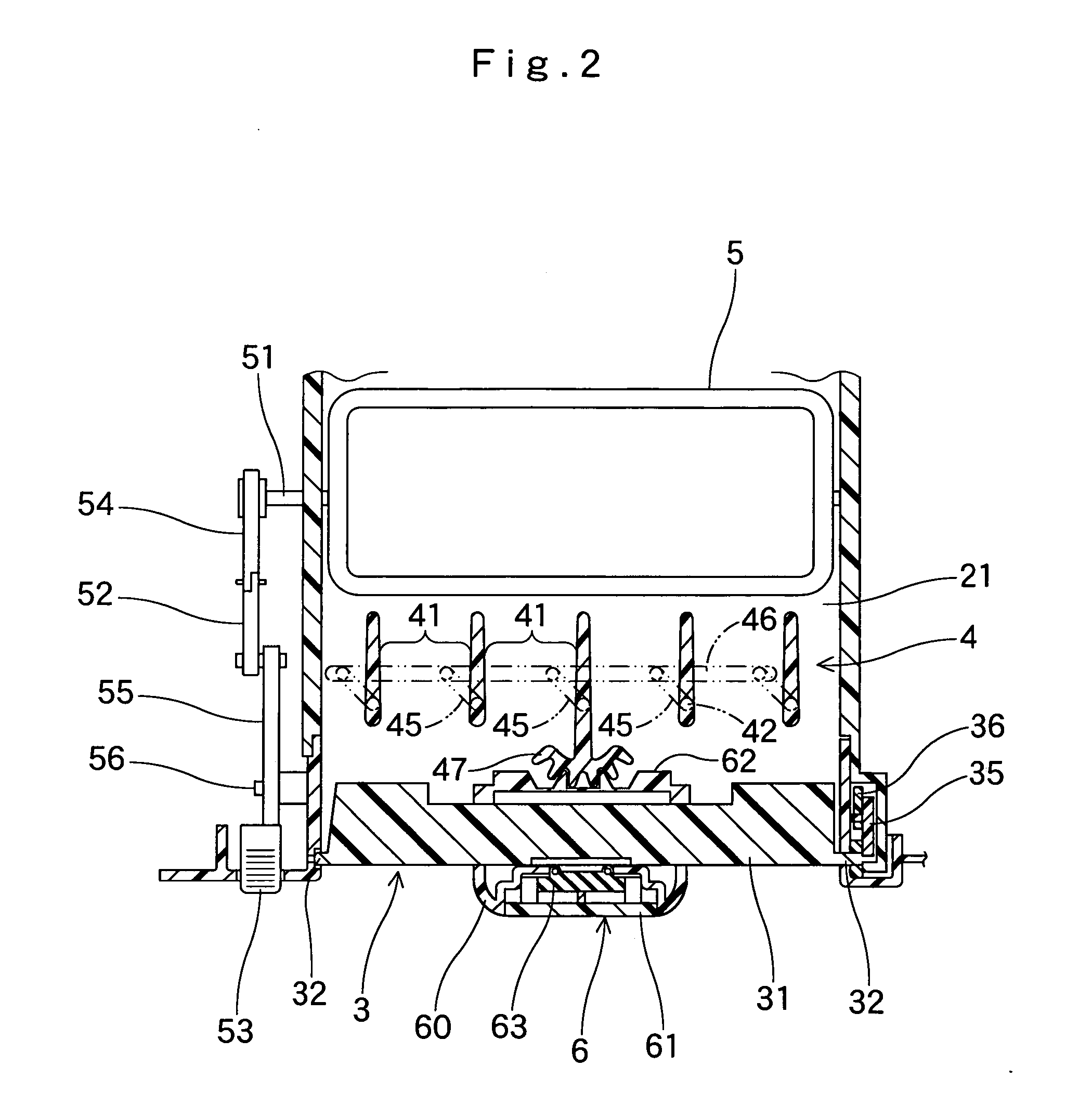
[0029]FIG. 1 is a front elevation of an air vent register embodying the present invention, and FIG. 2 is its cross section. FIG. 3 is a plan view of a horizontal fin 31 of a front movable louver structure 3, and FIG. 4 is an enlarged cross section of an operation knob 6 of the horizontal fin. FIG. 5 is an exploded perspective view of the knob 6.

[0030] In these drawings, reference numeral 1 generally denotes a bezel provided at its front with an outlet opening 11. Inside or at the backside of bezel 1 is a fitting region in which a later-described retainer 2 is fitted for connection with bezel 1. Left and right side walls of the inner side of the opening 11...


PUM


Abstract

An air vent register includes a front movable louver structure having a plurality of fins disposed side by side for rotation, a rear movable louver structure disposed at a rear of the front movable louver structure, the rear louver structure having a plurality of fins for rotation arranged side by side and extending orthogonally to the fins of the front louver structure, an operation knob mounted around one of the fins of the front louver structure in a slidable manner, a link mechanism linking the operation knob and the rear louver structure for rotating the fins of the rear louver structure in accordance with a sliding movement of the operation knob, and a rubber-like elastic element arranged between the operation knob and the fin of front movable louver structure equipped with the operation knob in an abutting manner to the fin and the operation knob, the elastic element comprising a projection abutting against the fin and having a through hole for increasing a deformable amount of the projection.

Description

[0001] The present application claims priority from Japanese Patent Application No. 2005-328831 of Endou, filed on Nov. 14, 2005, the disclosure of which is hereby incorporated into the present application by reference. BACKGROUND OF THE INVENTION [0002] 1. Field of the Invention [0003] The present invention relates to an air vent register used for ventilation of vehicle compartment or for an air outlet of air conditioner, and more particularly to an air vent register in which a knob is slidably mounted on one of fins in a front movable louver structure for adjusting the outlet direction of air. [0004] 2. Description of Related Art [0005] An air vent register of this kind is known for example in JP4-082645U. This air vent register includes a horizontal movable louver structure and a vertical movable louver structure arranged one behind another in its bezel defining an airflow channel, and an operation knob movably mounted on a central fin of the horizontal louver structure located f...

Claims


Application Information

Patent Timeline
IPC IPC(8): B60H1/34
CPCB60H1/3421B60H2001/3471
Inventor ENDOU, MASAHIRO
Owner HOWA PLASTICS CO LTD
Why Eureka
Try Eureka