Methods for manufacturing a paint roller with integrated core and cover

Inactive Publication Date: 2000-12-12
SEKAR CHANDRA
View PDF27 Cites 55 Cited by
  • Summary
  • Abstract
  • Description
  • Claims
  • Application Information

AI Technical Summary

Problems solved by technology

Such cores, however, and the paint rollers made out of them, would often fall apart during use or during cleaning, especially during cleaning with paint solvents (such as, for example, turpentine or mineral spirits, such paint solvents are well known in the art).
The obvious drawback of reusable cores formed in this manner is that they require a long assembly line, due to the need of a heater, and because the phenolic must be heated to a predetermined temperature, there is an obvious trade off between the number of heater stages and the speed of the line.
Additionally, while the resulting rollers are termed reusable because they do not separate when placed in paint solvents, any prolonged exposure to such solvents, does result in breakdown of the paint roller and/or separation of the layers.
Moreover, the manufacturing process for making phenolic core rollers is environmentally unfriendly.
For one, while prior art techniques use rolls of, e.g., chipboard or paper, the Garcia process requires preformed thermoplastic tubular cores which are considerably bulkier than rolls, more expensive to transport, and more difficult to handle.
Another drawback is the anticipated speed limit of the Garcia process dictated by the necessity that the heater, which advances along the core just in front of the fabric strip, move slow enough to insure softening of the p

Method used


Image

  • Methods for manufacturing a paint roller with integrated core and cover
  • Methods for manufacturing a paint roller with integrated core and cover
  • Methods for manufacturing a paint roller with integrated core and cover

Examples


first embodiment

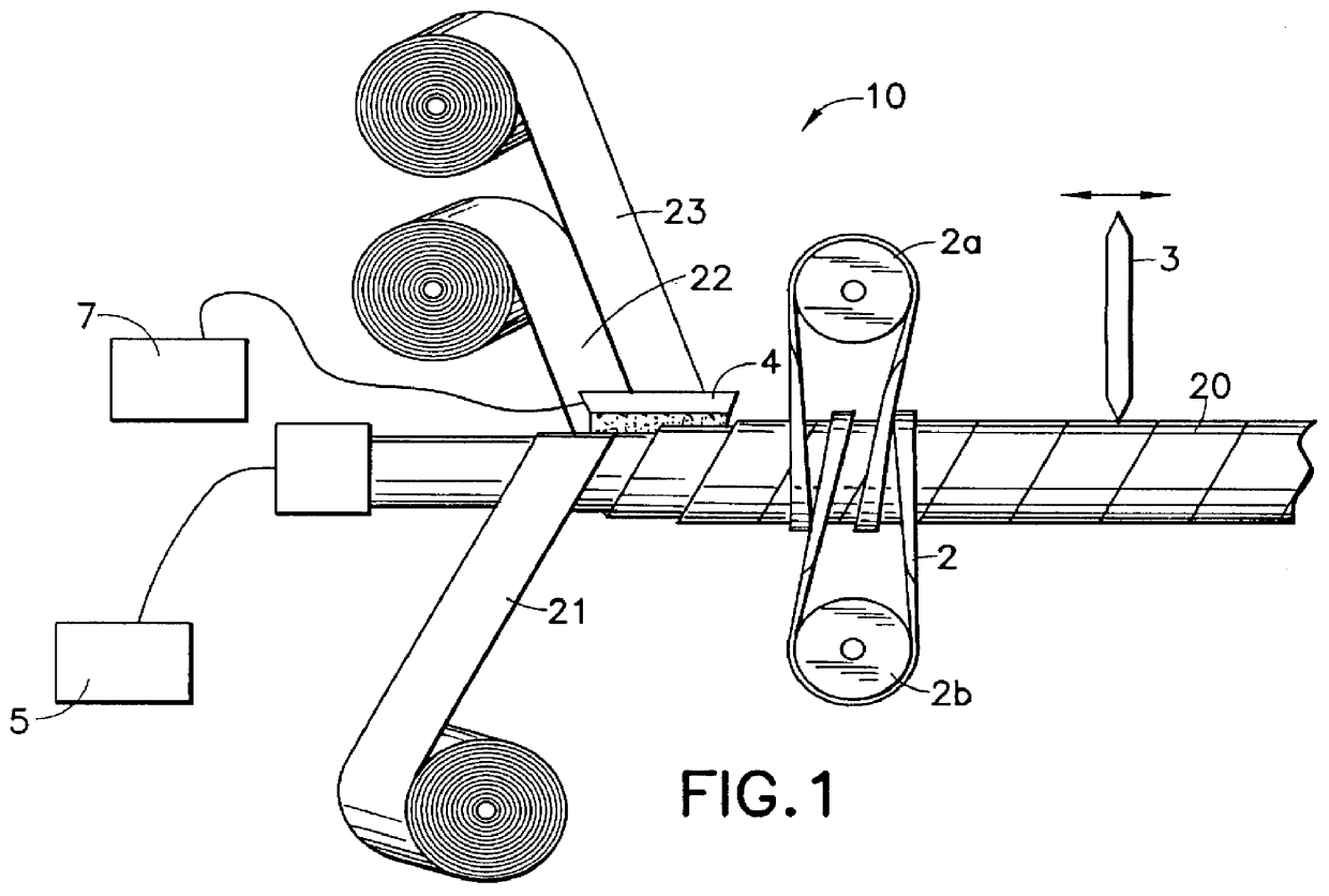
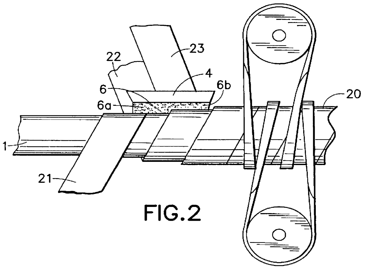
The first embodiment orientation of feed for the strips 21, 22 and cover 23, as shown in FIG. 2, permits the cover 23 to be advanced toward the mandrel 1 adjacent and parallel to the outer strip 22. Such positioning permits the use of a single head 4 that can apply adhesive 6a, 6b to the outer surface of the inner strip 21 and to the outer surface of the outer strip 22 simultaneously. Additionally, this positioning permits the adhesive 6a, 6b to be exposed uniformly and for a very short period prior to being sandwiched between the inner and outer strips 21, 22 or the outer strip 22 and the cover 23. Further, this positioning permits a very short assembly line for the continuous manufacturing process.

Second Embodiment

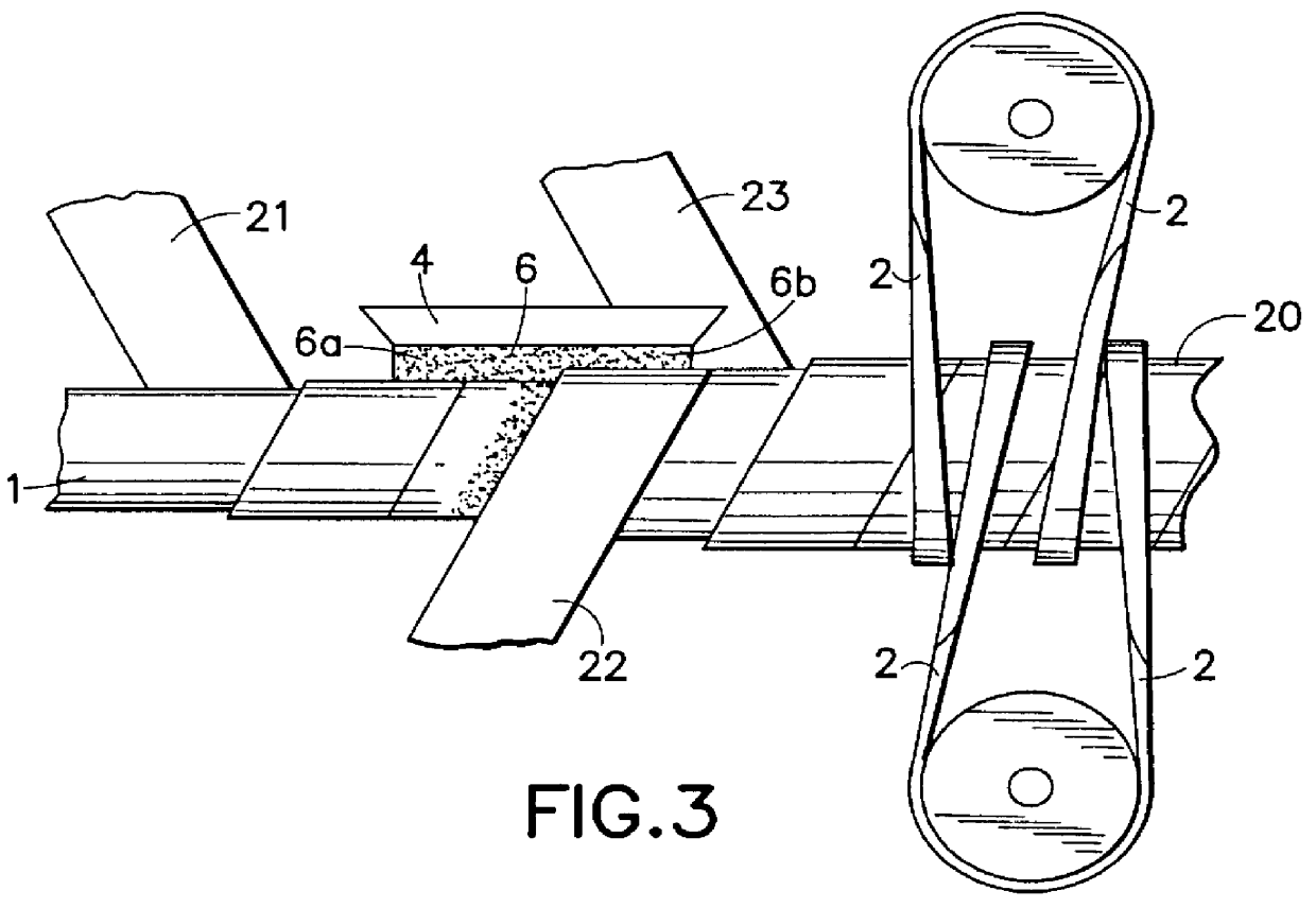
It is believed that providing an offset between the outer strip 22 and the cover 23 could yield an even sturdier product, a Ad method permitting such offset is disclosed. Turning now to a second embodiment, having a detail shown in FIG. 3, a continuous paint roller is ma...

second embodiment

The second embodiment does cause non-uniform exposure of the adhesive layer 6 prior to being sandwiched. The significance of the non-uniform exposure of the adhesive is unknown, however, if it should prove to be a problem, a multi-head system may be used to resolve it. For example, one head 4 may be used for the first layer 6a and a portion of the second layer 6b. A second head 4 may then be used to apply the remaining portion of the second adhesive layer 6b at a slightly higher temperature, thus compensating for the difference in exposure.

Third Embodiment

Turning now to a third embodiment, having a detail shown in FIG. 4, a continuous paint roller is manufactured from an inner strip of thermoplastic material 21, an outer strip of thermoplastic material 22, a cover 23, and an adhesive (not shown) applied from two heads 4a and 4b. The thermoplastic material is preferably polypropylene. The cover 23 may be a well-known fabric cover for a paint roller, which can be made of polyester.

third embodiment

The third embodiment differs from the first two in the orientation of feed for the strips 21, 22 and cover 23. The third embodiment consists of the shortest assembly line.

The inner strip 21 is helically advanced about the mandrel 1. As is well known, a lubricant may be applied to the inner surface of the inner strip 21 prior to winding on the mandrel 1. The outer strip 22 is helically advanced about the inner strip 21 in offset relation. The cover 23 is helically advanced about the outer strip 22, the cover may but need not be in offset relation.

Prior to forming the roller, two layers of the adhesive material (not shown) are applied. Two heads 4a, 4b provide adhesive material from a source of such material 7, such as an extruder. Head 4a applies a first layer of the adhesive to the inner surface of outer strip 22, while head 4b applies a second layer material to the outer surface of the outer strip 21.

Prior to the hardening and setting of the two layers of adhesive material, the bel...


PUM

PropertyMeasurementUnit
Diameteraaaaaaaaaa
Diameteraaaaaaaaaa
Lengthaaaaaaaaaa

Abstract

A reusable multi-strip laminate paint roller and method for manufacturing the same. The method comprising steps of: advancing a first strip of polypropylene material about a mandrel; advancing a second strip of polypropylene about a mandrel in offset relation to the first strip; advancing a cover about the second strip of polypropylene; providing a first adhesive layer (preferably a liquefied polypropylene) between the first and second strips of polypropylene; providing a second adhesive layer between the second strip of polypropylene and the cover; and applying a compressing force upon the cover urging the cover toward the second strip and simultaneously urging the second strip toward the first strip, thereby creating the continuous laminated paint roller. After forming of the continuously paint roller it is moved towards a cutter by a helical drive belt system. The continuously formed roller is then preferably cut into lengths for movement to a finishing station, and then cut into finished size paint rollers.

Description

This invention pertains to a method and apparatus for making paint rollers of the type used for applying paint to walls and the like. More specifically, the invention pertains to a method and apparatus for making paint rollers having thermoplastic (and preferably polypropylene) cores that are formed in a single-step continuous process.Prior ArtPaint rollers are widely used by professionals and amateurs for applying paint to walls, ceilings, and other surfaces. Typically the roller is used with an applicator having a handle terminating in a rotatable member to which the roller is secured. The roller itself generally comprises a paint absorbing and spreading cover affixed to a generally cylindrical core. The covers may be made from materials such as wool or polyester, and other cover materials that are well known in the art.Years ago paint rollers were manufactured using a paper or chipboard core. Some manufacturers still make such paper core paint rollers. The manufacture of such cor...

Claims


Application Information

Patent Timeline
IPC IPC(8): B05C17/02B29C53/58B29C53/00F16C13/00B29C53/60B29K23/00B29L31/32
CPCB05C17/0207B29C53/581B29C2793/009B29K2023/12Y10T29/49551B29L2031/324B29L2031/328Y10T29/49982Y10T29/49549B29K2623/12B05C17/02
Inventor SEKAR, CHANDRA
Owner SEKAR CHANDRA
Why Eureka
Try Eureka