Wire guide with cannula

a wire guide and cannula technology, applied in the direction of guide wires, manufacturing tools, catheters, etc., can solve the problems of excessive wear of drawing equipment, difficult and expensive combination of drawing and heat-treatment and/or pressure-treatment of cladding assemblies, damage to vessel linings, etc., to achieve sufficient pushability, sufficient flexibility and kink resistance, the effect of greater stiffness

Inactive Publication Date: 2011-06-30
COOK INC
View PDF38 Cites 52 Cited by
  • Summary
  • Abstract
  • Description
  • Claims
  • Application Information

AI Technical Summary

Benefits of technology

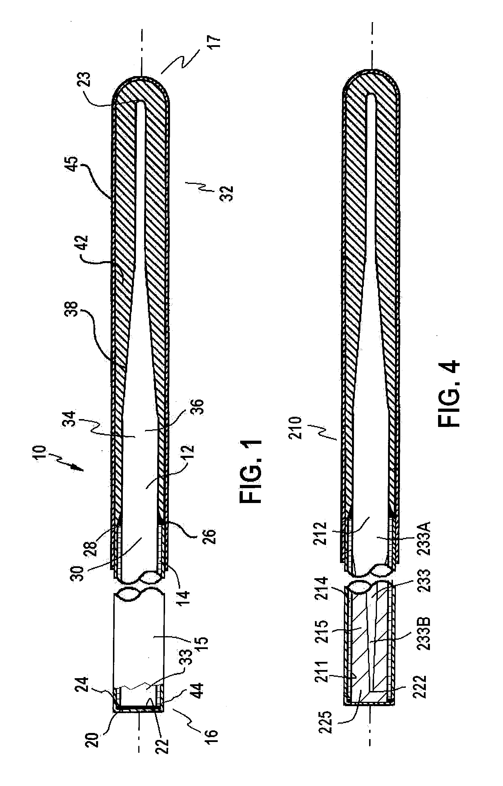
[0008]One aspect provides a wire guide having sufficient flexibility and kink resistance, as well as sufficient pushability. In one embodiment, the wire guide includes an elongated mandrel and a cannula having a stiffness greater than the mandrel stiffness. The mandrel can be made of a shape memory alloy such as Nitinol and the cannula can be made of a metal alloy such as stainless steel, platinum, palladium, a nickel-titanium, or combinations thereof. The cannula lumen is sized to receive the mandrel therein, and has a length relative to the length of the mandrel such that a portion of the mandrel extends distal to the cannula when received in the cannula lumen. The extended distal portion of the mandrel can permit the wire guide to have sufficient flexibility and kink resistance at its distal region, while the cannula can permit the wire guide to have sufficient pushability at its proximal region. The cannula can be attached, preferably by soldering or welding, along the length of the mandrel at least at one attachment joint. The extended distal portion of the mandrel can have a taper from a first diameter to a second diameter to form a distal tip of the wire guide. A proximal portion of the mandrel may also have a taper from a first diameter to a second diameter to improve the flexibility along the proximal region of the wire guide. The wire guide may also include a polymer coating surrounding the extended portion of the mandrel to further form the distal tip, a hydrophilic coating disposed on a portion of the polymer coating, a lubricious polymer coating disposed on at least one of a portion of the cannula or a portion of the extended portion of the wire guide, or any combination of coatings.
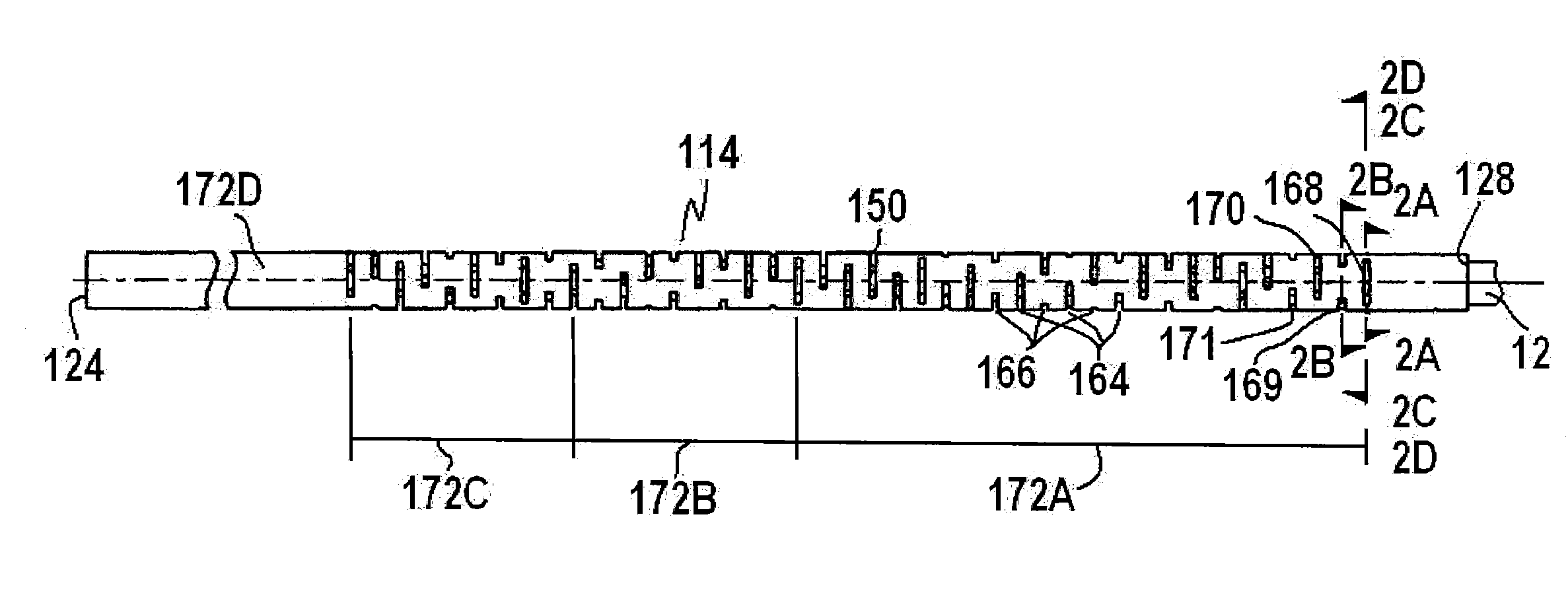
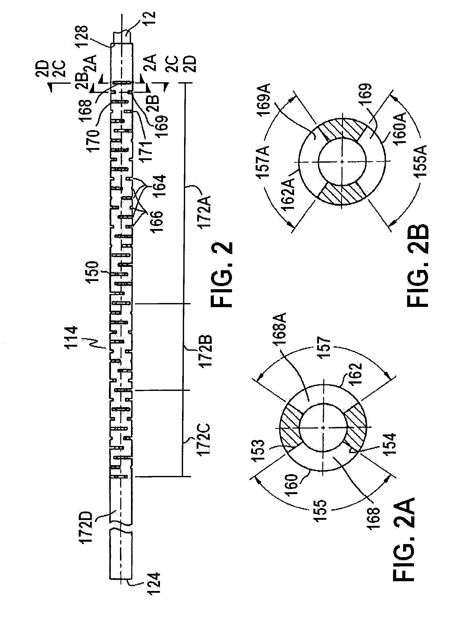
[0009]In yet another embodiment, the wire guide can further include a slotted cannula to improve the flexibility of the wire guide where the cannula is located. The slots are formed in the wall of the cannula and are circumferentially disposed along the cannula wall. The slots formed in the cannula wall can be transverse to the longitudinal axis of the wire guide. More than one slot can be formed along a single circumferential region such that a first slot is circumferentially spaced from a second slot. More than one series of slots can be formed in the wall of the cannula to vary the flexibility along the wire guide. The slot of a series can be spaced from an adjacent slot of the same series at a longitudinal distance. This longitudinal distance at a proximal portion of the cannula can be greater than the longitudinal distance at a distal portion of the cannula to increase the longitudinal flexibility along the wire guide. The slots of a series can be circumferentially positioned relative to one another at an angle to form a generally helical pattern along the cannula wall to vary the circumferential flexibility along the wire guide. Slots of a second series can be interposed between adjacent slots of a first series. The second series slots may be circumferentially positioned relative to each of the first series slots at an angle such that the second series slots are circumferentially offset from the first series.

Problems solved by technology

Efforts have been made to improve both the strength and the flexibility of wire guides to make them more suitable for their intended uses, but these two properties tend to be diametrically opposed to one another in that an increase in one usually involves a decrease in the other.
However, such wire guides are in some instances so stiff they can damage vessel linings when being advanced.
A combination of drawing and heat-treating and / or pressure-treating a cladded assembly is difficult and expensive, especially the manufacturing intensive steps to draw down fully to a wire guide size of about 0.018 inches.
There is also excessive wear on the drawing equipment due to the abrasiveness of the shape memory core.
This is problematic when the core wire alone has the desired flexibility, and the cladding covering material increases undesirably the stiffness of the distal end of the wire core.

Method used


Image

  • Wire guide with cannula
  • Wire guide with cannula
  • Wire guide with cannula

Examples


Embodiment Construction

[0018]In accordance with an embodiment of the present invention, a wire guide system includes a wire guide having sufficient flexibility and kink resistance, as well as sufficient pushability for use in a body vessel of a human or animal patient (“patient”).

[0019]The terms proximal and distal are used herein to refer to portions of a wire guide. As used herein, the term “distal” is defined as that portion of the wire guide closest to the end of the wire guide inserted into the patient's body lumen. The term “proximal” is defined as that portion of the wire guide closest to the end of the wire guide that is not inserted into the patient's body lumen. The terms distally and proximally are used herein to refer to directions along an axis joining the proximal and distal portions of the wire guide (“axial direction”). For example, proximal movement is movement towards the proximal portion of the wire guide. Distal movement is movement towards the distal portion of the wire guide.

[0020]Th...


PUM

PropertyMeasurementUnit
sizeaaaaaaaaaa
diameteraaaaaaaaaa
diameteraaaaaaaaaa

Abstract

The present invention generally relates to a medical surgical device and specifically a wire guide for percutaneous placement within a body lumen. The wire guide includes an elongated mandrel having sufficient flexibility and kink resistance and a cannula having a stiffness greater than the mandrel stiffness for sufficient pushability. The mandrel extends through the cannula and has a portion extending distal thereto to form a distal tip of the wire guide. The wire guide can further include a slotted cannula to improve the flexibility of the wire guide at the proximal portion of the wire guide. The slots can be arranged in various patterns for increased flexibility along the longitudinal length of the cannula, as well as increased circumferential flexibility along the wire guide. The mandrel may also have a proximally tapered portion to improve the flexibility of the wire guide at the proximal portion of the wire guide.

Description

TECHNICAL FIELD[0001]The present invention generally relates to a medical surgical device and specifically a wire guide for percutaneous placement within a body lumen. The flexibility of the wire guide can be varied by a cannula coaxially displaced on the wire core.BACKGROUND[0002]Wire guides are commonly used in vascular procedures, such as angioplasty procedures, diagnostic and interventional procedures, percutaneous access procedures, or radiological and neuroradiological procedures in general, to introduce a wide variety of medical devices into the vascular system. For example, wire guides are used for advancing intraluminal devices such as stent delivery catheters, balloon dilation catheters, atherectomy catheters, and the like within body lumens. Typically, the wire guide is positioned inside the inner lumen of an introducer catheter. The wire guide is advanced out of the distal end of the introducer catheter into the patient until the distal end of the wire guide reaches the ...

Claims


Application Information

Patent Timeline
Patent Type & Authority Applications(United States)
IPC IPC(8): A61M25/09A61L15/50B23P17/04
CPCA61M25/09033Y10T29/49826A61M2025/0915
Inventor CAGE, LOGAN M.WEEKS, AARONKAY, JR., THOMAS A.ELSESSER, JAMES C.
Owner COOK INC
Why Eureka
Try Eureka