Cable tray system

a cable tray and cable technology, applied in the direction of rod connections, fastening means, electrical equipment, etc., to achieve the effect of efficiently and accurately designing and installing a wide range of three-dimensional cable trays

Active Publication Date: 2017-12-12
JAMES C WHITE CO INC
View PDF23 Cites 30 Cited by
  • Summary
  • Abstract
  • Description
  • Claims
  • Application Information

AI Technical Summary

Benefits of technology

[0010]This combination of pre-configured and job-site, cut-to-fit components form the basis of a cable tray system. Its kit-like nature and the specific features of its components enables the design of a cable tra

Problems solved by technology

More often than not, however, previously installed or permanent structures, such as support columns, walls, and other cable trays, are obstacles to the installation

Method used


Image

  • Cable tray system
  • Cable tray system
  • Cable tray system

Examples


Embodiment Construction

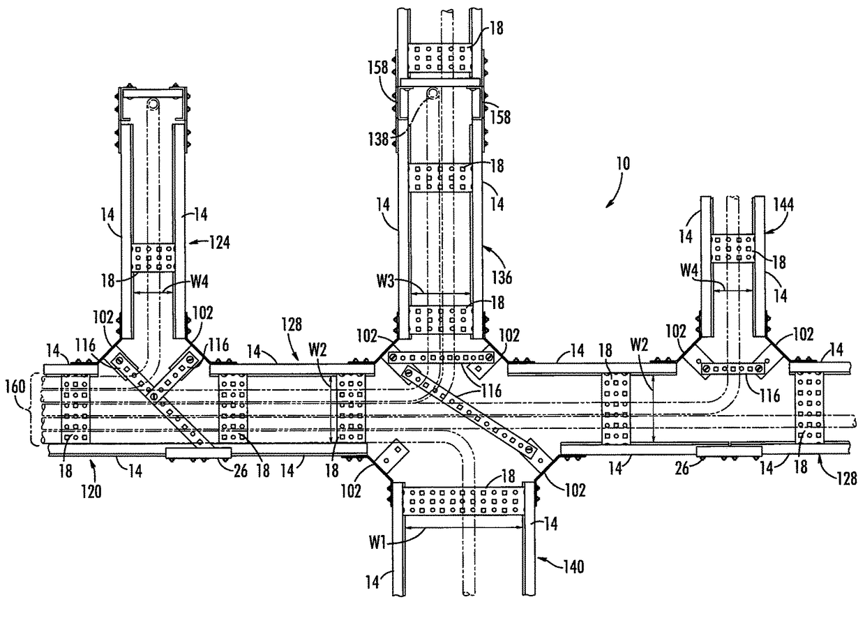
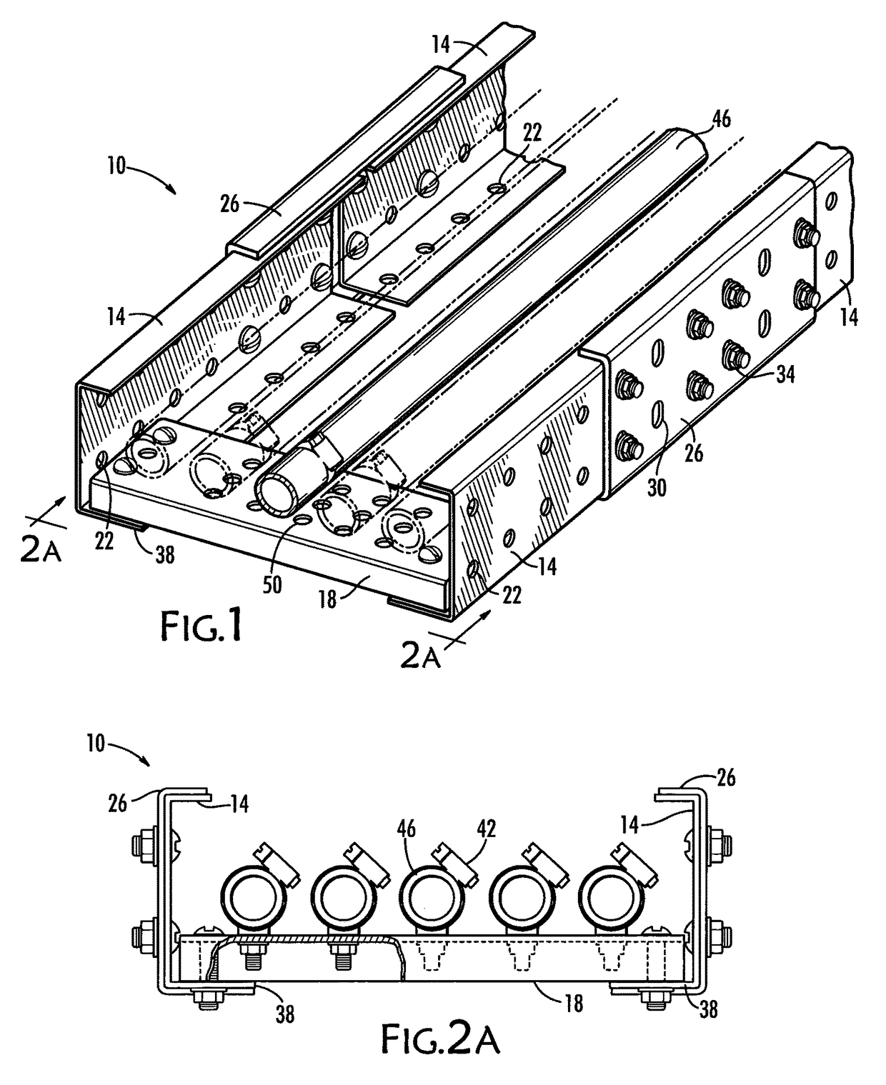
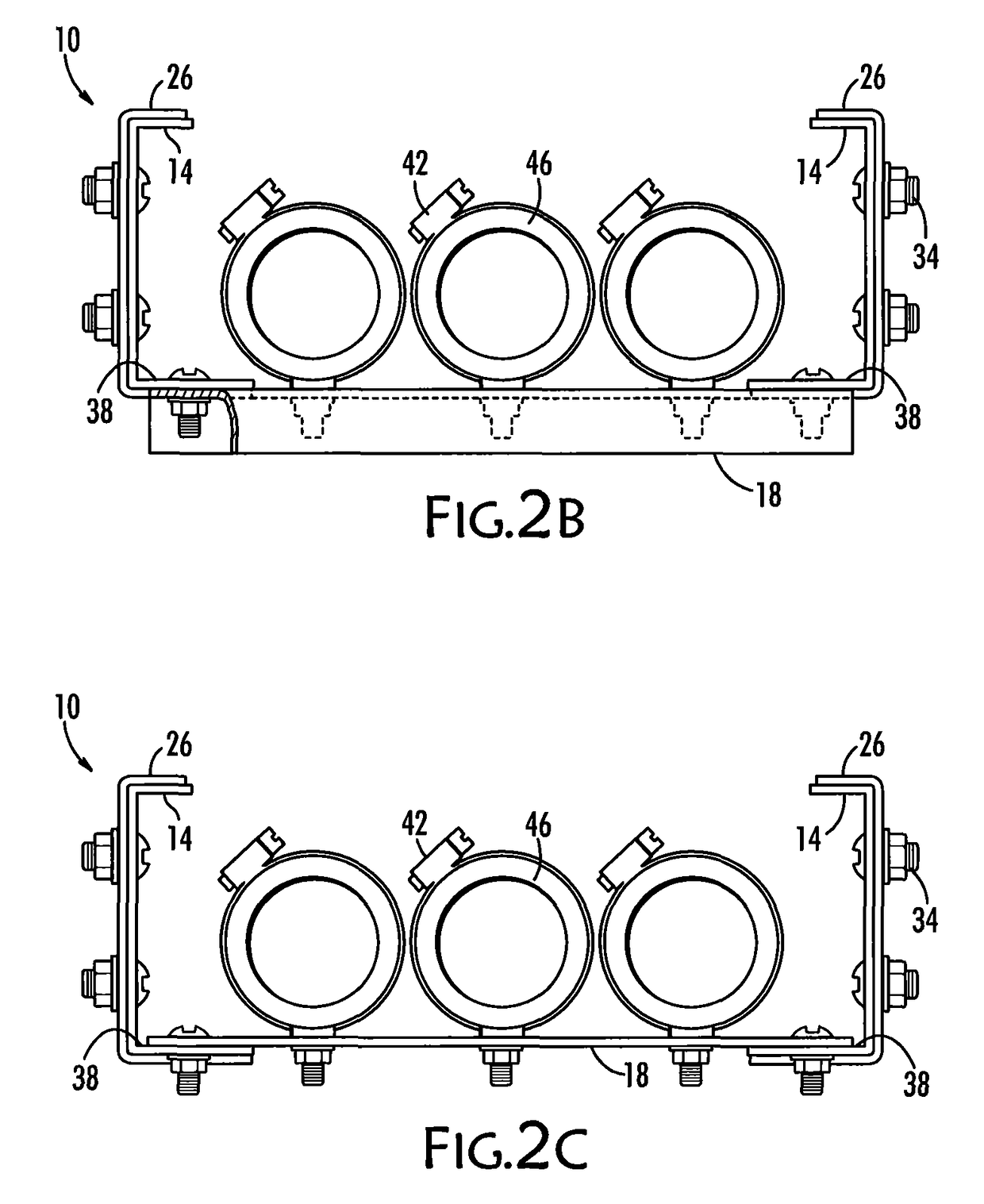
[0022]The present invention is a cable tray system. The present cable tray system is useful for the design and installation of an elevated cable tray that crosses a space while avoiding other structures in that space as it runs from one part of that space to another. For example, when cables run from one or more buildings to another, more than one cable tray may be established to provide elevated, rigid paths for the cables and which cable trays avoid obstacles and each other as they cross that space, thereby protecting the cables while also keeping them organized during construction, verification, inspection, maintenance and repair.

[0023]By the term system, it is meant that the components cooperate with each other so that a designer and installer can design and install a cable tray meeting any of innumerable different requirements simply by selecting from among those components the number and size of components necessary and then cutting and connecting those components according to...


PUM


Abstract

A collection of components for a cable tray system provide the components and basic hardware for assembling and installing a cable tray that can change direction in three dimensions to avoid obstacles or other cables' trays while negotiating a designated space. Components of the cable tray system may be modular, that is, pre-configured for ease of assembly, such as vertical kits and horizontal bend kits, while others are supplied in lengths for cutting them to fit jobsite requirements, such as rails and rungs. Both components provide an inherent framework that facilitates conceptualization and construction of a cable tray system at the jobsite with flexibility and simplicity to allow the present cable tray system to be employed more efficiently and accurately.

Description

PRIORITY CLAIM[0001]NoneBACKGROUND OF THE INVENTION[0002]Cable trays (sometimes called cable races) are found in commercial and industrial facilities, power generation facilities, manufacturing plants, and the like. These trays and their related hardware are used to support, guide, contain, and help manage cables, tubes, pipes, conduits, and wires that must be run from one part of the facility or plant to another. Examples of cable trays may be found in U.S. Pat. No. 4,232,845, U.S. Pat. No. 3,137,468, U.S. Pat. No. 4,432,519 and U.S. Pat. No. 6,498,296, which are incorporated herein by reference.[0003]The primary requirement for a completed cable tray system is structural rigidity. In many applications, the cable tray system is also designed to minimize or eliminate electrical arcing between connected parts of the system by maintaining electrically conductive continuity in the event that the system becomes electrically energized.[0004]Cable trays typically are formed from linear ru...

Claims


Application Information

Patent Timeline
IPC IPC(8): F16L3/26F16L3/08F16B7/18F16L3/22
CPCF16L3/26F16B7/182F16B7/18F16L3/08F16L3/22H02G3/0418H02G3/0437H02G3/0456H02G3/0608H02G3/263H02G3/32
Inventor WHITE, THOMAS C.
Owner JAMES C WHITE CO INC
Why Eureka
Try Eureka