Metal gasket

a technology of metal gaskets and gaskets, which is applied in the direction of engine seals, sealing arrangements, machines/engines, etc., can solve the problems of reducing the rigidity of engine components such as the cylinder block and the cylinder head, affecting the sealing performance of the engine, and uneven surface pressure around the cylinder bore, etc., to achieve the effect of preventing cracking of the bead, high sealing performance and sufficient capability

Inactive Publication Date: 2006-07-27
ISHIKAWA GASKET CO LTD
View PDF9 Cites 10 Cited by
  • Summary
  • Abstract
  • Description
  • Claims
  • Application Information

AI Technical Summary

Benefits of technology

[0027] Therefore, high sealing performance for the cylinder bore can be achieved and also, enough capability for following the repeated vertical movements of the cylinder head during engine operation can be achieved. Accordingly, cracking of the bead can be prevented.

Problems solved by technology

Because engine materials are aluminum-alloyed or reduced in weight due to a reduction in the weight of engines, the rigidity of the engine members such as the cylinder block and cylinder head tends to decline.
Therefore, in the case of using a bead whose sealing surface pressure is locally high, or a bead whose capability for following the movement in a vertical direction of the cylinder head (following capability) during the engine operation is poor, the top of the bead of the gasket is contacted with the cylinder head (or cylinder block) due to the movement of the cylinder head so that Brinelling (depression) occurs in the cylinder head (or cylinder block).
As a result, the sealing surface pressure around the cylinder bore becomes uneven, and the sealing performance declines.
However, when the spring steel is used for a part of the bead of a primary sealing which requires high surface pressure, the bead displays cracks due to repeated vertical movements of the cylinder head during the engine operation.

Method used


Image

  • Metal gasket
  • Metal gasket
  • Metal gasket

Examples


first embodiment

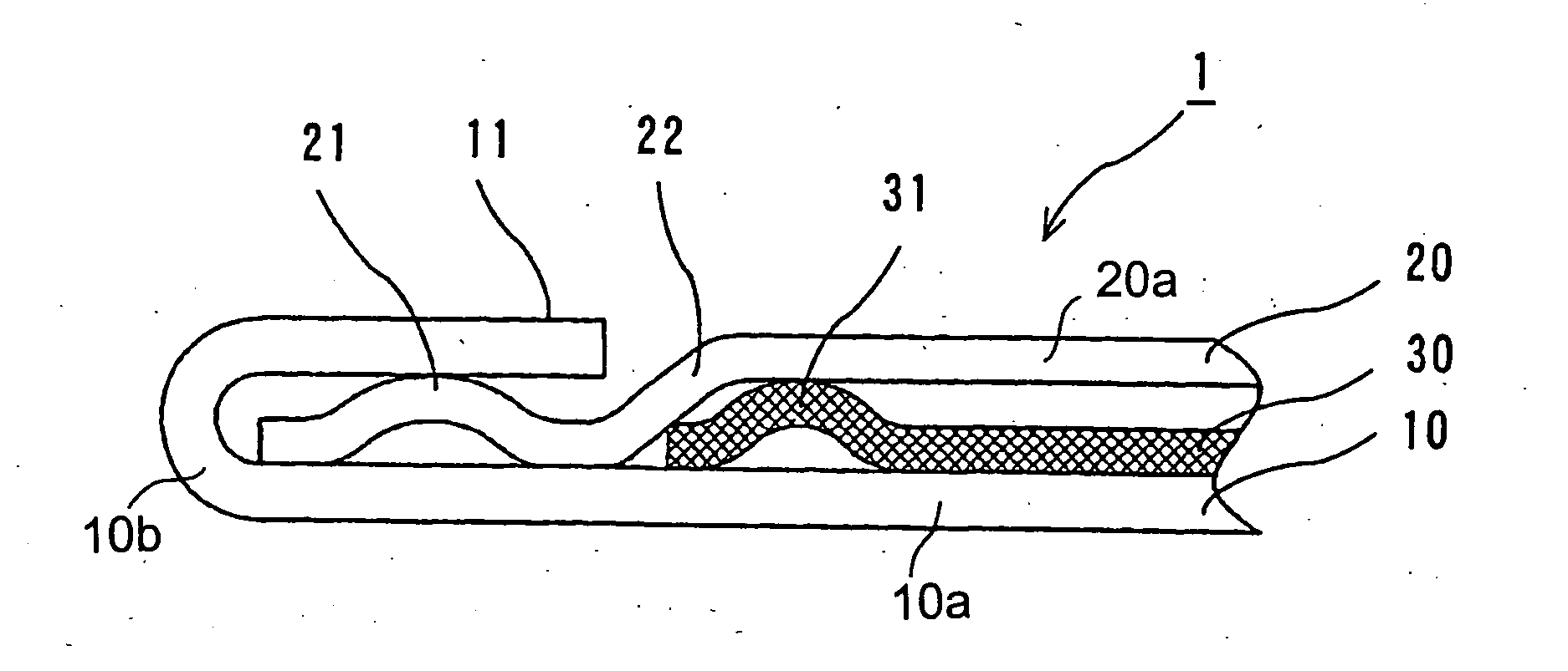
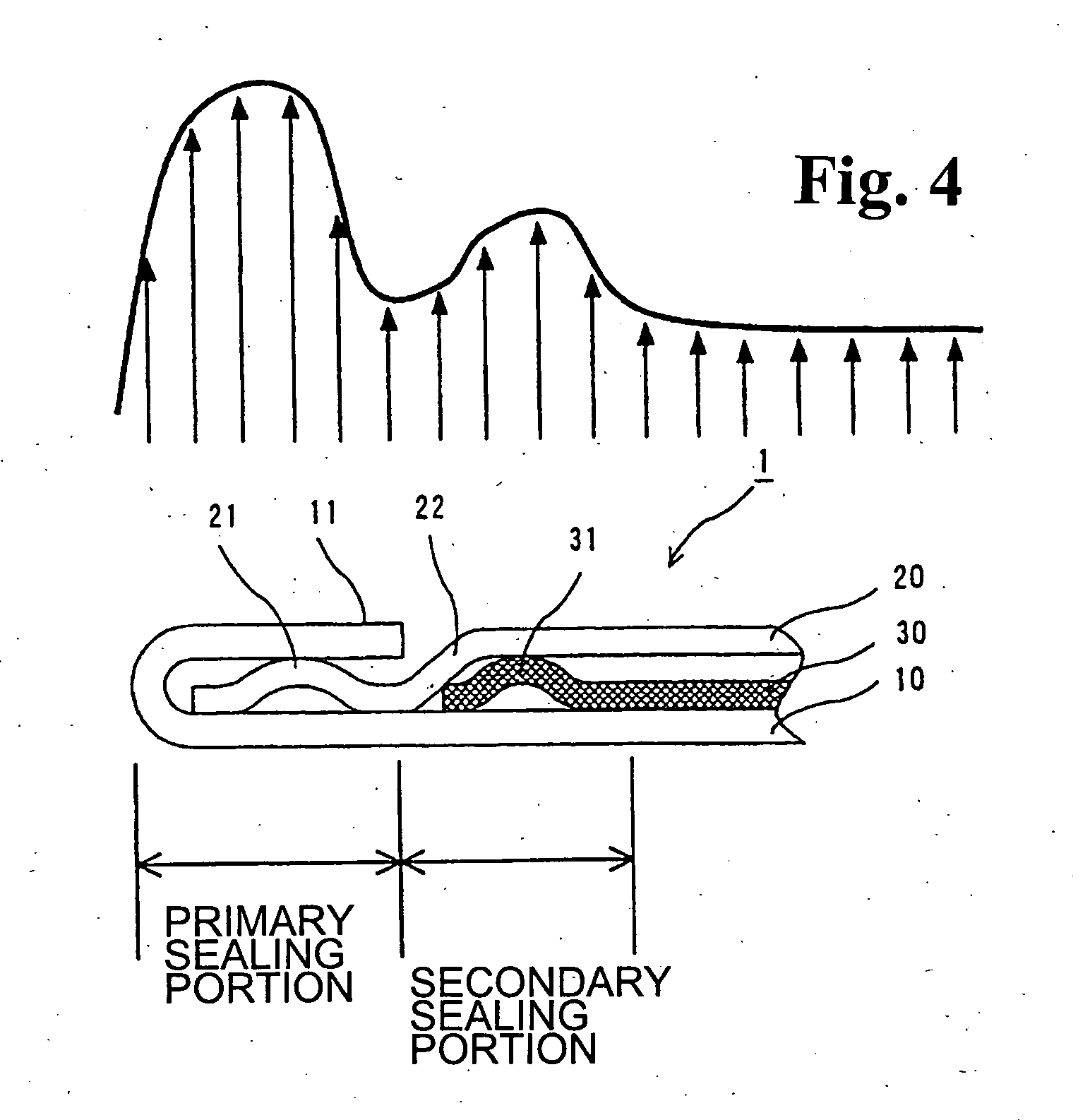
[0035] As shown in FIG. 1, a metal gasket 1 is constituted by a first metal plate 10, second metal plate 20, and third metal plate 30. The first metal plate 10 is made of a mild steel plate, the second metal plate 20 is made of an annealing steel such as a stainless annealing material (annealing material), and the third metal plate 30 is made of a spring steel such as a stainless well-tempered material (spring steel plate), respectively.

[0036] A folded portion (grommet) 11 of the first metal plate 10 is provided around a cylinder bore which is a sealing-target hole. Also, the second metal plate 20 is provided with a first full bead 21 which becomes a projection or depression (projection in FIG. 1) to the folded portion 11 side, and is disposed inside the folded portion 11. A half bead 22 is provided around the first full bead 21, and a second full bead 31 provided in the third metal plate 30 is abutting against the half bead 22.

[0037] The first metal plate 10 also includes a base ...

second embodiment

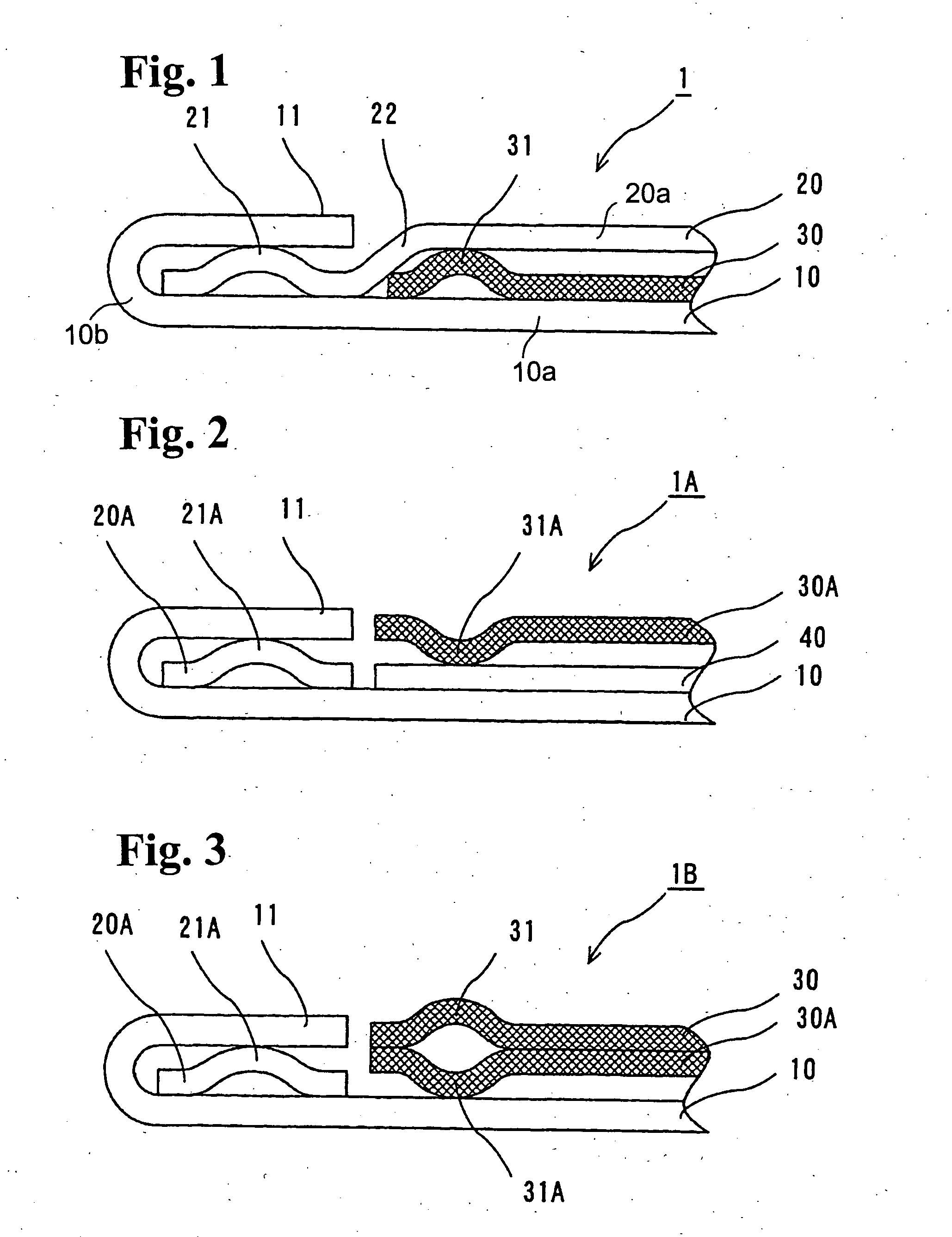
[0045] Also, as shown in FIG. 2, a metal gasket 1A is constituted by: first metal plate 10; second metal plate 20A in the form of a ring; third metal plate 30A; and fourth metal plate 40. The first metal plate 10 and fourth metal plate 40 are made of the mild steel plate; the second metal plate 20A is made of the annealing steel; and the third metal plate 30A is made of the spring steel, respectively.

[0046] The folded portion 11 of the first metal plate 10 is provided around the cylinder bore which is the sealing-target hole. Also, the first full bead 21A which becomes the projection or depression (projection in FIG. 2) to the folded portion 11 side is provided on the annular second metal plate 20A, and is disposed inside the folded portion 11. The fourth metal plate 40 is provided around the first full bead 21A. In addition, the second full bead 31A is provided in the third metal plate 30A in such a way so that it is depressed to the folded portion 11 side. The metal gasket 1A is ...

third embodiment

[0050] Also, as shown in FIG. 3, a metal gasket 1B is constituted by: first metal plate 10; second metal plate 20A; and two third metal plates 30, 30A. The first metal plate 10 is made of the mild steel plate; the second metal plate 20A is made of the annealing steel; and the third metal plates 30, 30A are made of a spring material, respectively.

[0051] The folded portion 11 of the first metal plate 10 is provided around the cylinder bore which is the sealing-target hole. Also, the first full bead 21A which becomes the projection or depression (projection in FIG. 3) to the folded portion 11 side is provided on the second metal plate 20A, and is disposed inside the folded portion 11. The second full beads 31, 31A whose depressed portions are facing each other are provided in the two third metal plates 30, 30A around the first full bead 21A and outside the folded portion 11. The metal gasket 1B is constituted by laminating the first-third metal plates 10, 20A, 30 and 30A.

[0052] Even ...


PUM


Abstract

A metal gasket for providing a seal between a cylinder head and a cylinder block of an engine is a laminate of a first metal plate, a second metal plate, and a third metal plate. The first metal plate has a folded portion for positioning around a cylinder bore, the second metal plate has a first full bead inside the folded portion to provide a primary sealing portion, and the third metal plate has a second full bead provided around an outer circumference of the first full bead to provide a secondary sealing portion. The primary sealing portion has a primary sealing surface pressure, and the secondary sealing portion has a secondary sealing surface pressure less than the primary sealing surface pressure. The secondary sealing portion provides enhanced following capability during engine operation.

Description

BACKGROUND OF THE INVENTION AND RELATED ART STATEMENT [0001] The present invention relates to a metal gasket to be installed between two engine members, such as a cylinder head and the cylinder block of an engine, so as to seal therebetween. [0002] When a joint surface of the cylinder head and cylinder block (cylinder body) of an auto engine (internal combustion) is sealed, a metal cylinder head gasket is installed therebetween and seals combustion gas, coolant water, or lubricating oil. [0003] When the periphery of a cylinder bore (combustion chamber bore) is sealed, high-temperature combustion gas is required to be sealed in such that a folded portion (grommet portion) is provided by folding back the marginal part of the bore, and also multiple beads are provided. Accordingly, the periphery of the cylinder bore is sealed by multiple sealing lines. [0004] One of the cylinder head gaskets proposed is a cylinder head gasket comprising: the folded portion provided in the first plate; ...

Claims


Application Information

Patent Timeline
Patent Type & Authority Applications(United States)
IPC IPC(8): F02F11/00
CPCF02F11/002F16J15/0825F16J2015/0837F02F11/00F16J15/02F16J15/08
Inventor UDAGAWA, TSUNEKAZUYAMADA, YOSHIOMIYAOH, YOSHIO
Owner ISHIKAWA GASKET CO LTD
Why Eureka
Try Eureka