Transmit power allocation in wireless communication devices

Inactive Publication Date: 2007-05-17
MOTOROLA MOBILITY LLC
View PDF34 Cites 181 Cited by
  • Summary
  • Abstract
  • Description
  • Claims
  • Application Information

AI Technical Summary

Problems solved by technology

In wireless communication devices, power management and specific absorption rate (SAR) regulation compliance are ever present challenges, particularly in view of the

Method used


Image

  • Transmit power allocation in wireless communication devices
  • Transmit power allocation in wireless communication devices
  • Transmit power allocation in wireless communication devices

Examples


Embodiment Construction

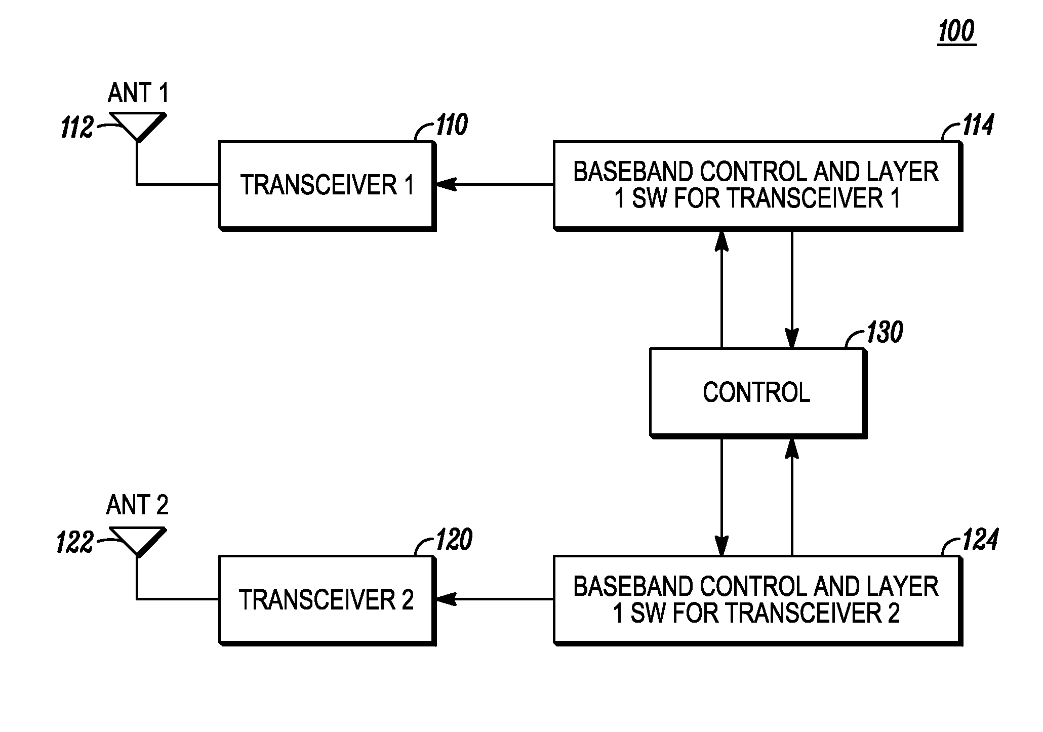
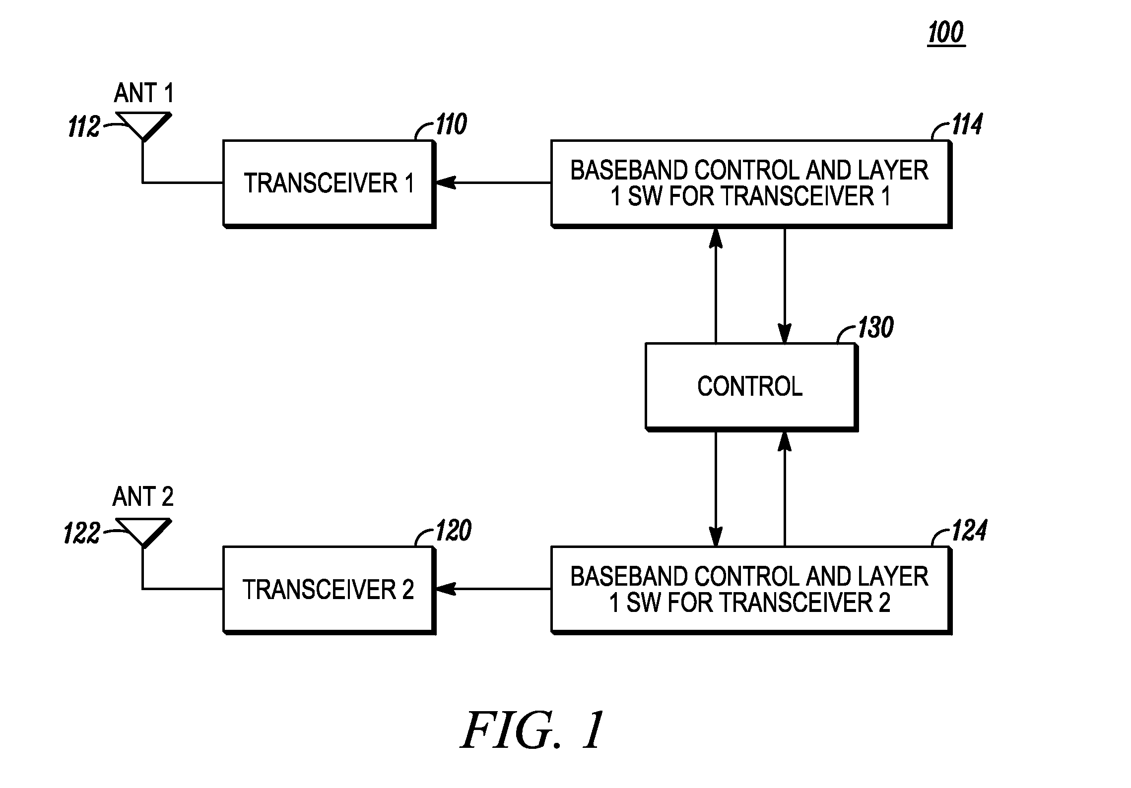
[0007]FIG. 1 illustrates a portable wireless communication device 100. Such devices may be embodied as a multi-mode cellular communications handset, for example, a Global System for Mobile Communications (GSM) / Universal Mobile Telecommunications System (UMTS) compliant handset. In other embodiments, the multi-mode communication device may include a WLAN and / or a WAN transceiver with one or more cellular transceivers. The multi-mode wireless communication device is not intended to be limited by any of the exemplary types of transmitters or transceivers disclosed herein. The particular transmitter type and / or the particular protocol with which the transmitter complies are not particularly relevant.

[0008] In FIG. 1, the portable wireless communication device 100 comprises generally a first transmitter 110 coupled to a first antenna 112 and a second transmitter 120 coupled to a second antenna 122. While the first and second transmitters in FIG. 1 are coupled to corresponding antennas, ...


PUM


Abstract

A portable multimode wireless communication device (100) including first and second transmitters (110, 120) coupled to corresponding antennas or to a common antenna. The portable device controls (130) an output power of one or both of the first and second transmitters so that a characteristic, for example, the combined specific absorption rate, of the transmitters of the portable multimode wireless communication device does not exceed a specified limit.

Description

FIELD OF THE DISCLOSURE [0001] The present disclosure relates generally to wireless communications, and more particularly to power management in wireless mobile communication devices, for example, in CDMA / GSM multi-mode cellular handsets. BACKGROUND OF THE DISCLOSURE [0002] Multi-mode cellular communication devices commonly include multiple transceivers, for example, in CDMA and GSM transceivers that operate simultaneously. These multi-mode devices may also include a WIFI and / or a Bluetooth (BT) transceiver. In wireless communication devices, power management and specific absorption rate (SAR) regulation compliance are ever present challenges, particularly in view of the trend toward multi-mode devices and the increasing requirement of wireless communication network operators for transceivers having higher output power capabilities. [0003] The various aspects, features and advantages of the instant disclosure will become more fully apparent to those having ordinary skill in the art ...

Claims


Application Information

Patent Timeline
IPC IPC(8): H04B1/04H04B1/02H01Q11/12
CPCH04B1/3838H04B2001/0416H04W52/34H04W52/367
Inventor ALBERTH, WILLIAM P. JR.WELNICK, WILLIAM E.
Owner MOTOROLA MOBILITY LLC
Why Eureka
Try Eureka