Liquid crystal display device

a technology of liquid crystal display panel and driving circuit, which is applied in the direction of static indicating devices, instruments, etc., can solve the problems of inability to determine instantaneously whether a pixel is off, the outermost portion of the display screen (display area) and the current cellular phone or portable information terminal is generally limited in the number of display pixels. achieve the effect of easy and less cost, and without increasing the scale of the driving circui

Inactive Publication Date: 2007-05-24
SASAKI NOBUYUKI
View PDF2 Cites 0 Cited by
  • Summary
  • Abstract
  • Description
  • Claims
  • Application Information

AI Technical Summary

Benefits of technology

[0012] In this manner, the waveforms applied to the segment electrodes and common electrodes responsible for the frame display can be formed based on the input signal to the driver IC. This permits any type of controller or driver to provide the frame display outside the display screen in an easy and less-costly manner without increasing the scale of the driving circuit.

Problems solved by technology

Such a liquid crystal display device has a problem that an observer cannot instantaneously determine whether a pixel is OFF because it is located outside a display screen or because an OFF signal is inputted thereto.
Therefore, when a photo or game graphic with a black background is displayed on such a panel, the outermost portion of the display screen (display area) is unrecognizable.
On the other hand, the current cellular phones or portable information terminals are generally limited in the number of display pixels in order to expedite the display of information provided via network services or by add-on applications.
However, commonly used liquid crystal drivers and controllers are not equipped with such a capability so that liquid crystal panels adapted for the frame display based on this method are limited.
In addition, there is another problem that the IC having such a capability is more expensive than the common ICs.
This imposes restriction on the specification of the liquid crystal display device.
In addition, a significant cost must be borne in order to utilize the IC having such a capability.

Method used


Image

  • Liquid crystal display device
  • Liquid crystal display device
  • Liquid crystal display device

Examples


embodiment

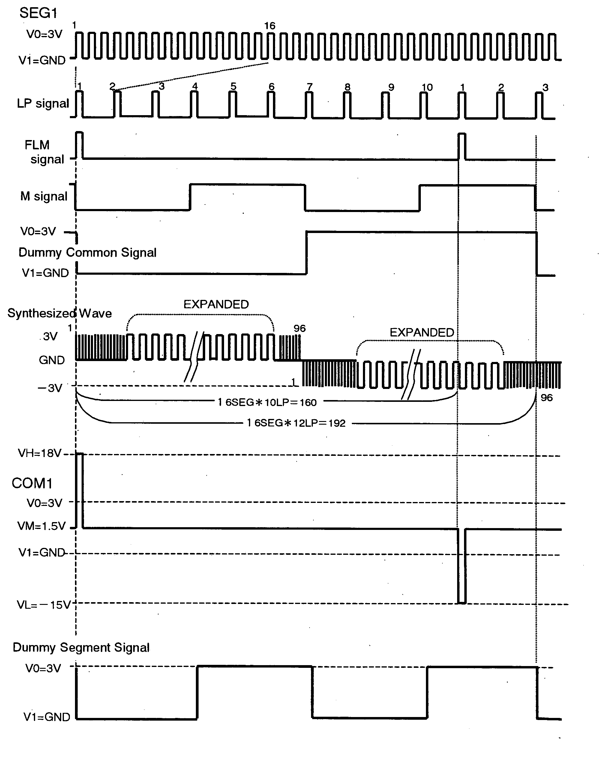
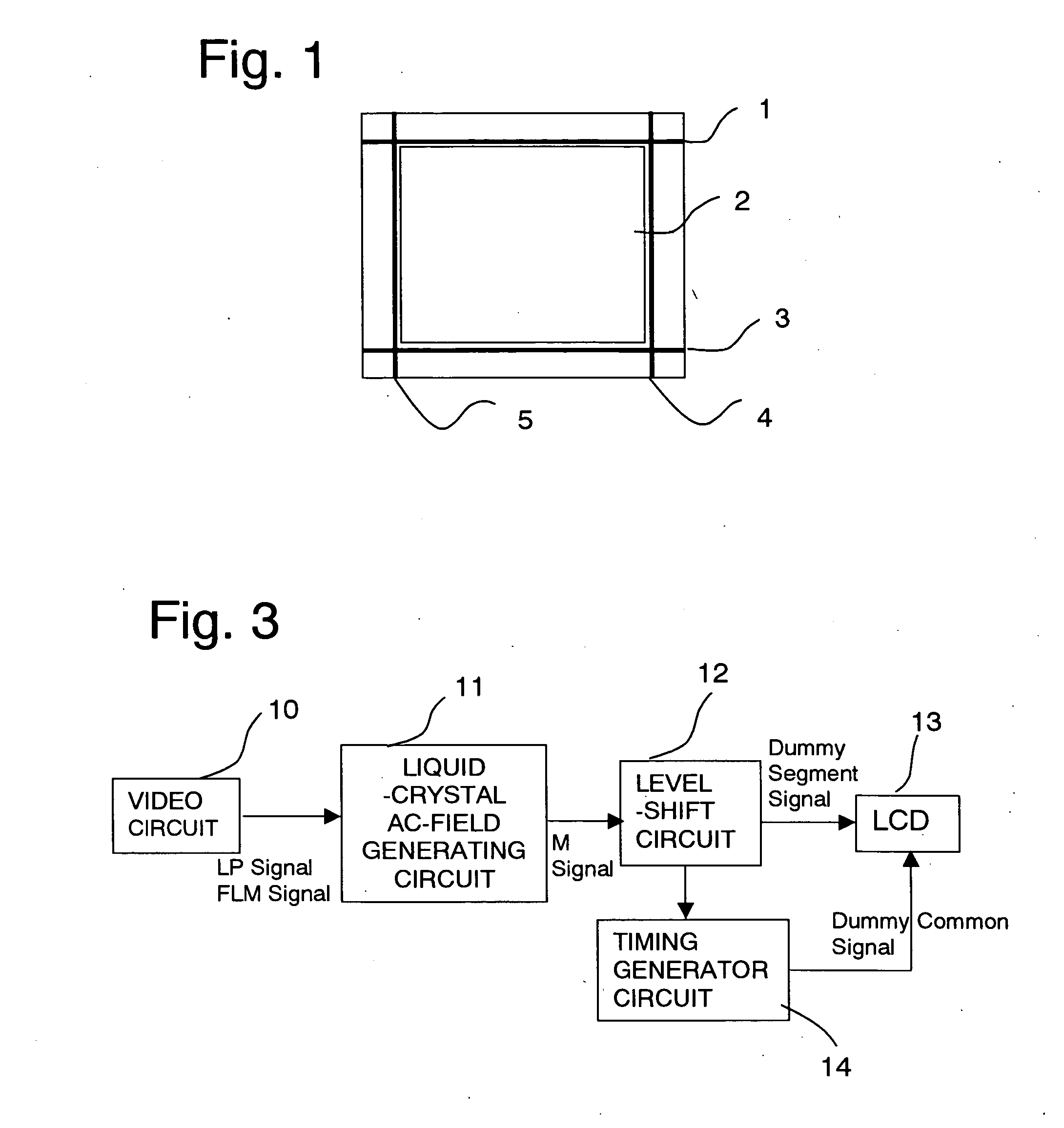
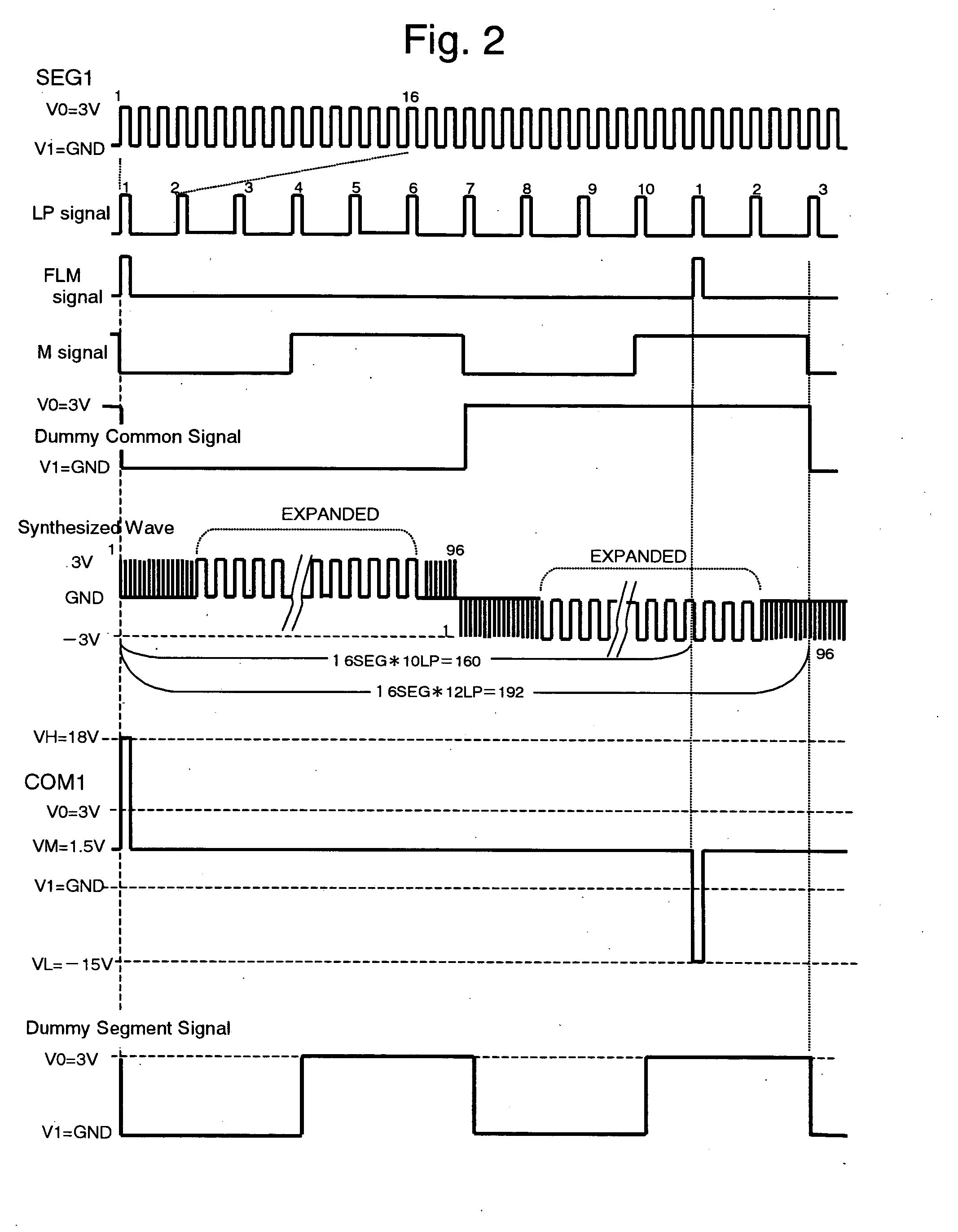
[0021]FIG. 1 schematically shows a construction of a display screen (wiring pattern) of a liquid crystal display device according to an embodiment of the invention. As shown in FIG. 1, a display screen 2 of a liquid crystal panel is essentially composed of m×n pixels. In a screen portion, m segment electrode wirings formed on a transparent plate and n common electrode wirings formed on a transparent counter plate intersect with one another to define the pixels. The segment electrode wirings and the common electrode wirings are applied with a liquid crystal control signal (driving signal) for image display from unillustrated segment driver IC and common driver IC, respectively. Dummy segment wirings 4, 5 are laid on laterally opposite sides externally of the aforesaid m×n pixels (display screen 2). Dummy common wirings 1, 3 are also laid on vertically opposite sides externally of the m×n pixels. The dummy segment wirings 4, 5 are applied with a signal waveform exceeding a selection v...


PUM

PropertyMeasurementUnit
transparentaaaaaaaaaa
timeaaaaaaaaaa
voltageaaaaaaaaaa

Abstract

In a case where a frame display is provided on a display screen of a liquid crystal panel, the prior art necessitates data for frame display to be directly written to all the display data or 2 screenful of data to be prepared and overwritten on each other. To overcome this problem, a liquid crystal display device of the invention has an arrangement wherein a segment electrode and a common electrode constituting a pixel to be driven for normal image display are applied with a driving waveform from a driver IC, and wherein a common electrode to be placed in a normally ON state is applied with a waveform exceeding a selection voltage of any segment signal waveform for liquid crystal selection while a segment electrode to be placed in a normally ON state is applied with a waveform exceeding a selection voltage of any common signal for liquid crystal selection. This permits a frame to be displayed on the display screen.

Description

BACKGROUND-OF THE INVENTION [0001] The present invention relates to a driving device for liquid crystal display panel of a passive drive system and to a liquid crystal display device and an electronic device employing the same. [0002] A passive-drive liquid crystal display panel widely used in electronic devices has a structure wherein a liquid crystal layer is sealed between a transparent plate formed with a plurality of line-shaped common electrodes and a transparent counter plate formed with a plurality of line-shaped segment electrodes. Individual intersections of the common electrodes and the segment electrodes define individual pixels which constitute a display screen. That is, the display screen of m×n pixels is essentially composed of m segment electrodes and n common electrodes. ON / OFF control of each pixel is accomplished by way of a signal (driving signal waveform) applied to the segment electrode and the common electrode. Such a liquid crystal display device has a proble...

Claims


Application Information

Patent Timeline
Patent Type & Authority Applications(United States)
IPC IPC(8): G09G3/36G02F1/133G09G3/20
CPCG09G3/3622G09G2310/0232G09G2310/06
Inventor SASAKI, NOBUYUKI
Owner SASAKI NOBUYUKI
Why Eureka
Try Eureka