Catheter balloon liner with variable thickness and method for making same

a catheter and variable thickness technology, applied in the field of catheters, can solve the problems of reducing the service life of the catheter, so as to improve the service life and improve the high rupture pressure. , the effect of reducing the number of defects

Inactive Publication Date: 2007-05-24
LIM FLORENCIA +1
View PDF22 Cites 20 Cited by
  • Summary
  • Abstract
  • Description
  • Claims
  • Application Information

AI Technical Summary

Benefits of technology

[0008] This invention is directed to a method of making a catheter balloon liner, and a balloon catheter including the liner, in which the liner of a catheter balloon is formed by increasing the inner diameter of a first end section of a tubular member, so that the tubular member has a first end section with an inner diameter less than the inner diameter of a central section of the tube. The first end section may preferably have a diameter sized to coincide with the smaller outer diameter of the catheter shaft at the distal end of the balloon, and the liner is bonded thereto form at least a portion of a skirt section of the balloon, providing a skirt section with an improved high rupture pressure. By selecting a tubular member with dimensions for eliminating or minimizing the gap between the liner and the catheter shaft at the distal end of the balloon, the shortcomings resulting from mismatch bonding are ameliorated. Further, the liner can be expanded radially at the opposite end to also accommodate the larger outer diameter of the catheter shaft at the proximal end of the balloon, eliminating or minimizing the same shortcomings. Thus, the liner is modified from a constant diameter tubular member to a tubular member having varying radial dimensions in an undeformed state at various locations along the balloon's longitudinal location.
[0010] The balloon of the present invention preferably has a wall thickness variation at the distal portion of the liner adjacent the bonded region compared with the thickness of the working section of the liner. Increasing the thickness of the liner at a first end portion, and preferably the distal end portion, in comparison with the central or working portion of the balloon liner, compensates for the thinning of the region adjacent the bonding regions due to the laser bonding techniques. The thicker wall fortifies the liner in the event of thin spots or high stress concentrations and improves the integrity of the balloon at elevated pressures. In a preferred embodiment the thickness of the balloon liner is greater at each end of the balloon adjacent the bonding region compared with the thickness of the liner at the working section of the balloon spaced from the tapered regions. In another embodiment, the liner is thicker at a first end, such as the distal end where the greatest stress concentrations statistically occur, and thinner at the working section and proximal section.
[0012] The distal end section of the substantially non porous elastomeric tubular member preferably forms at least a portion of the distal tapered section of the balloon that fits over and adheres to the catheter shaft, and also preferably is sized radially to eliminate or minimize a gap between the inner diameter of the elastomeric liner and the outer diameter of the catheter shaft in an undeformed state prior to catheter assembly / inflation. The proximal end section may preferably be sized to eliminate or minimize the gap between the catheter shaft at its outer diameter and the inner diameter of the proximal end of the elastomeric liner. The elastomeric liner may change inner diameters between the distal end portion and the central working portion at a step, or may alternatively gradually taper from a first inner diameter and thickness at a first end to a second inner diameter and thickness at a middle portion, and possibly a third inner diameter and thickness at a second end.
[0013] In a preferred embodiment the distal end section of the elastomeric tubular liner mates with the catheter shaft without a gap therebetween in an undeformed state, and where the distal end section has a greater wall thickness compared to the central portion of the balloon. This configuration results in a liner with an improved rupture resistance after bonding the liner to the catheter. The high rupture pressure of the distal tapered section of the balloon adjacent the bonding region allows the balloon to be inflated at relatively higher inflation pressures. Moreover, the liner is formed of a smaller initial outer and inner diameters than other conventional liners because the liners are sized to accommodate the catheter shaft's inner tubular member in the undeformed state rather than the catheter's outer tubular member. This reduction can result in a lower profile liner at the distal end and ultimately a lower balloon profile at the distal end of the balloon.

Problems solved by technology

One difficulty has been providing an ePTFE balloon with sufficiently high rupture pressure.
Some liner bonding techniques such as laser bonding the liner tubing to the outer surfaces of the catheter shaft results in wall thinning of the tubular liner in proximity with the bonding area.
This reduction in wall thickness of the liner can be uneven and result in thin spots or weakened areas that place the integrity of the balloon at risk.
Upon inflation of the balloon to elevated pressures of eight atmospheres or higher, these weaknesses due to the liner thinning at the bonding surfaces may lead to early rupture of the balloon.

Method used


Image

  • Catheter balloon liner with variable thickness and method for making same
  • Catheter balloon liner with variable thickness and method for making same
  • Catheter balloon liner with variable thickness and method for making same

Examples


Embodiment Construction

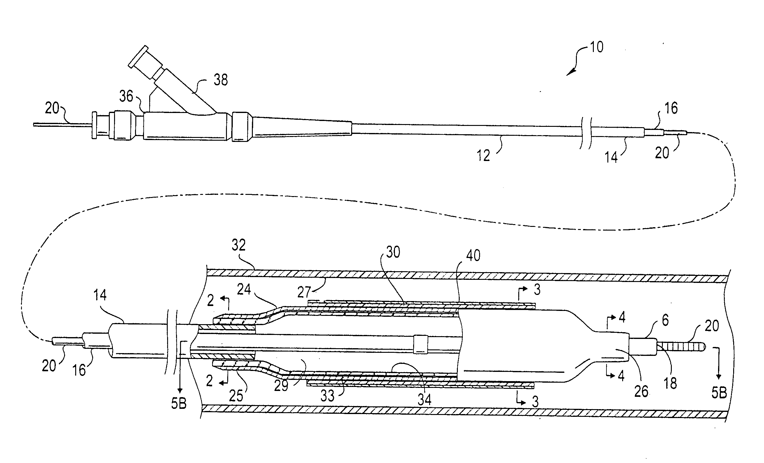
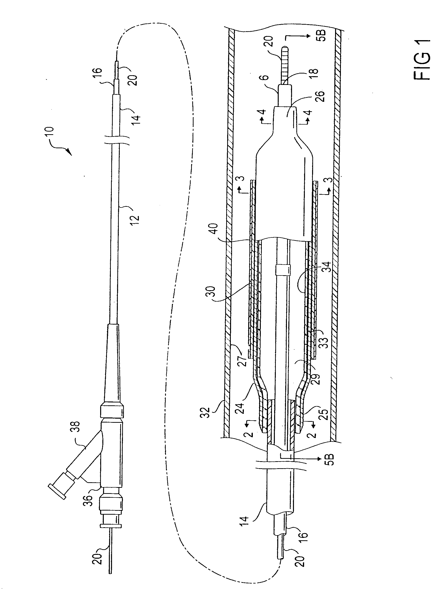
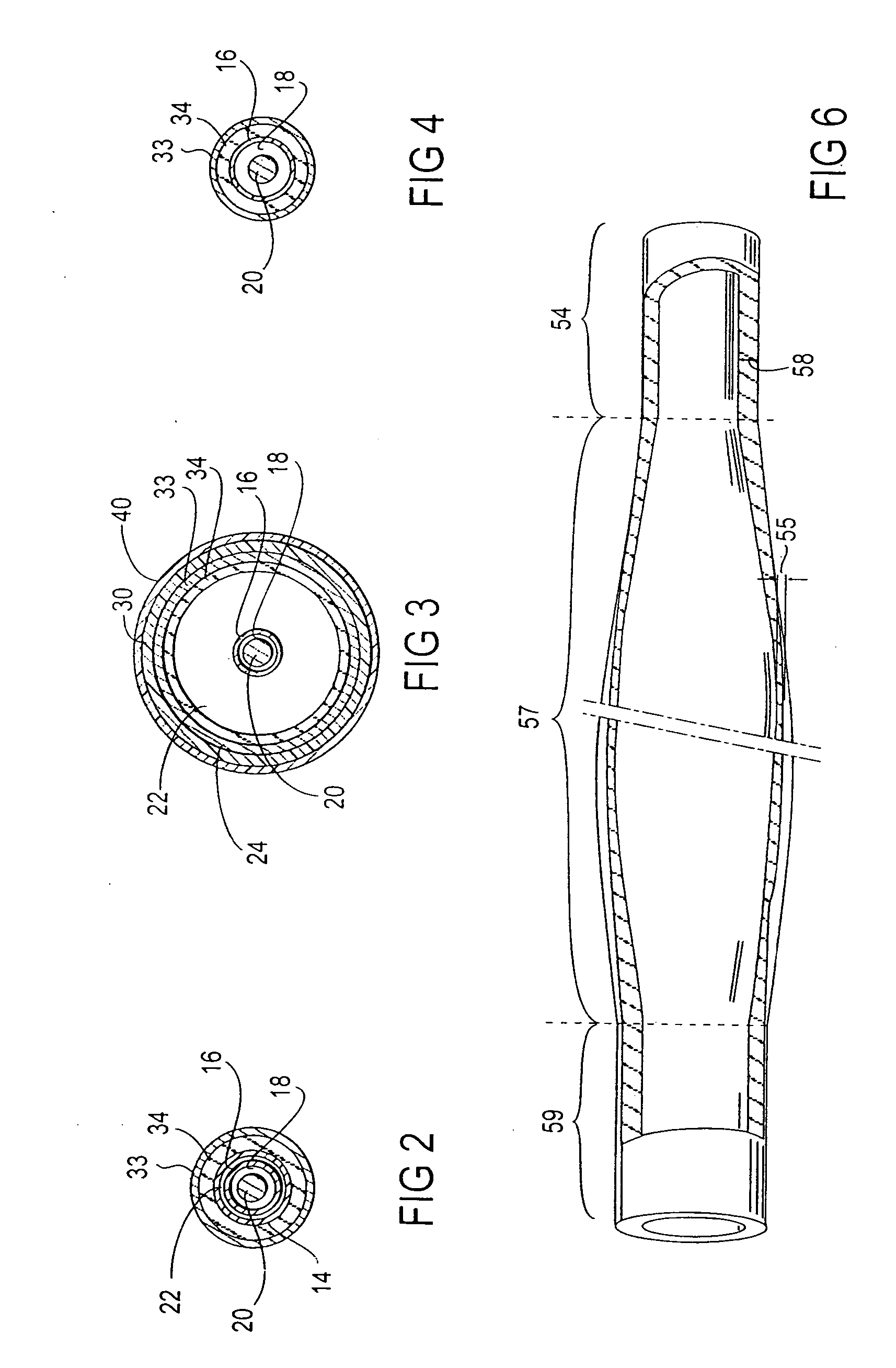
[0026]FIG. 1 illustrates an over the wire type stent delivery balloon catheter 10 embodying features of the invention. Catheter 10 generally comprises an elongated catheter shaft 12 having an outer tubular member 14 and an inner tubular member 16. Inner tubular member 16 defines a guidewire lumen 18 configured to slidingly receive a guidewire 20, and the coaxial relationship between outer tubular member 14 and inner tubular member 16 defines annular inflation lumen 22, as best shown in FIG. 2 illustrating a transverse cross section view of the distal end of the catheter shown in FIG. 1, taken along line 22. An inflatable balloon 24 disposed on a distal section of catheter shaft 12 has a proximal skirt section 25 sealingly secured to the distal end of outer tubular member 14 and a distal skirt section 26 sealingly secured to the distal end of inner tubular member 16, so that its interior is in fluid communication with inflation lumen 22. An adapter 36 at the proximal end of catheter ...


PUM


Abstract

A method of making a catheter balloon, and a balloon catheter formed thereby, in which a layer of a catheter balloon is formed by providing a tubular member to serve as a non porous liner for cooperation with a polymeric tube, and enlarging radially a central or working section of the tubular member such that a first end of the tubular member is smaller in the radial direction with respect to the working section. The tubular member may also have a thickness at the working section that is less than a thickness of the first and second end portions. The first end section of the tubular member is bonded to a catheter shaft having a first outer diameter to form at least a portion of a skirt section of the balloon, and the second end section is bonded to the catheter shaft having a second outer diameter to form a portion of a skirt section, where the skirt sections have an improved high rupture pressure.

Description

BACKGROUND OF THE INVENTION [0001] This invention generally relates to catheters, and particularly intravascular catheters for use in percutaneous transluminal coronary angioplasty (PTCA) or for the delivery of stents. [0002] In percutaneous transluminal coronary angioplasty (PTCA) procedures a guiding catheter is advanced in the patient's vasculature until the distal tip of the guiding catheter is seated in the ostium of a desired coronary artery. A guidewire is first advanced out of the distal end of the guiding catheter into the patient's coronary artery until the distal end of the guidewire crosses a lesion to be dilated. A dilatation catheter, having an inflatable balloon on the distal portion thereof, is advanced into the patient's coronary anatomy over the previously introduced guidewire until the balloon of the dilatation catheter is properly positioned across the lesion. Once properly positioned, the dilatation balloon is inflated with inflation fluid one or more times to a...

Claims


Application Information

Patent Timeline
Patent Type & Authority Applications(United States)
IPC IPC(8): A61M29/00A61M25/00
CPCA61M25/1029A61M25/1034A61M2025/1075
Inventor LIM, FLORENCIAWANG, EDWIN
Owner LIM FLORENCIA
Why Eureka
Try Eureka