Catheter balloon liner with variable thickness and method for making same

a catheter and variable thickness technology, applied in the field of catheters, can solve the problems of reducing the service life of the catheter, so as to improve the service life and improve the high rupture pressure. , the effect of reducing the number of defects

Inactive Publication Date: 2007-02-13
ABBOTT CARDIOVASCULAR
View PDF35 Cites 61 Cited by
  • Summary
  • Abstract
  • Description
  • Claims
  • Application Information

AI Technical Summary

Benefits of technology

[0008]This invention is directed to a method of making a catheter balloon liner, and a balloon catheter including the liner, in which the liner of a catheter balloon is formed by increasing the inner diameter of a first end section of a tubular member, so that the tubular member has a first end section with an inner diameter less than the inner diameter of a central section of the tube. The first end section may preferably have a diameter sized to coincide with the smaller outer diameter of the catheter shaft at the distal end of the balloon, and the liner is bonded thereto form at least a portion of a skirt section of the balloon, providing a skirt section with an ...

Problems solved by technology

One difficulty has been providing an ePTFE balloon with sufficiently high rupture pressure.
Some liner bonding techniques such as laser bonding the liner tubing to the outer surfaces of the catheter shaft results in wall thinning of the tubular liner in proximity with the bonding area.
This reduction in wall thi...

Method used


Image

  • Catheter balloon liner with variable thickness and method for making same
  • Catheter balloon liner with variable thickness and method for making same
  • Catheter balloon liner with variable thickness and method for making same

Examples


Embodiment Construction

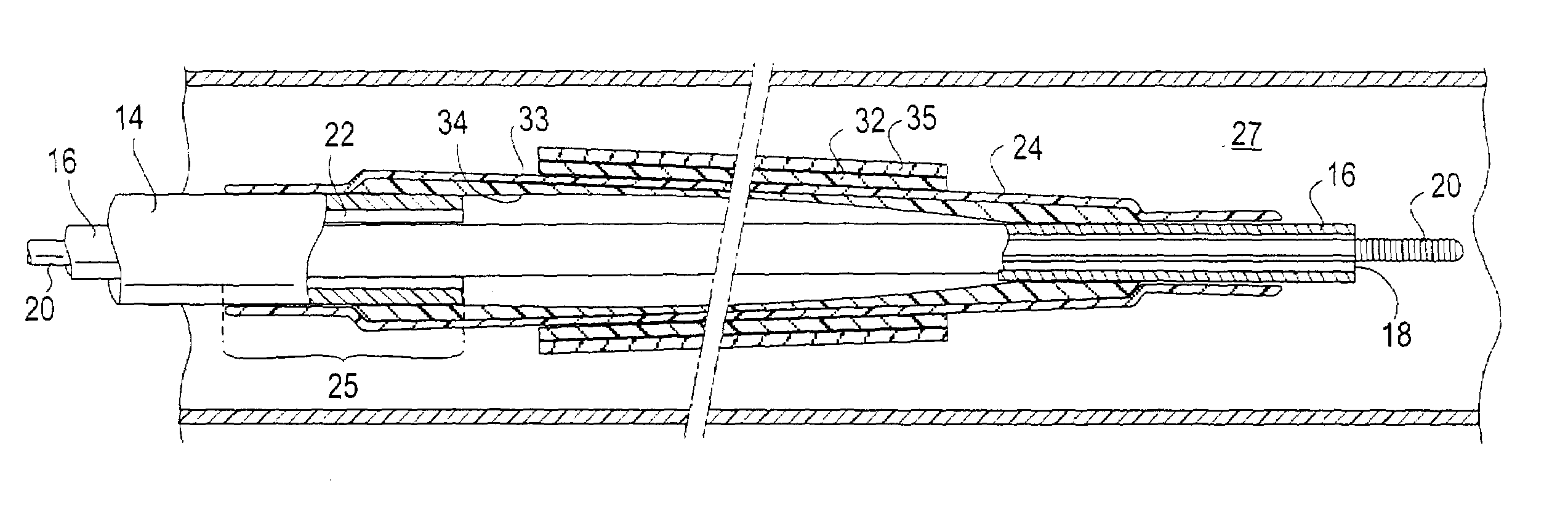
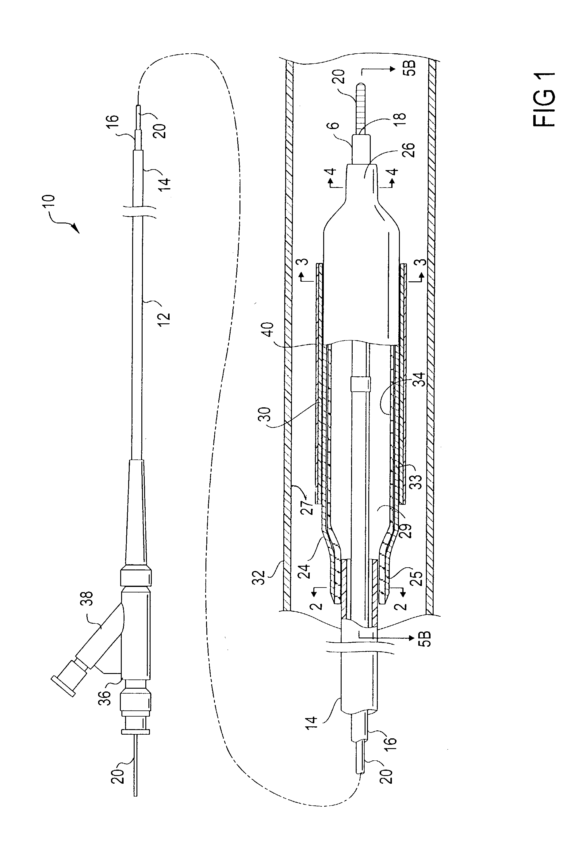
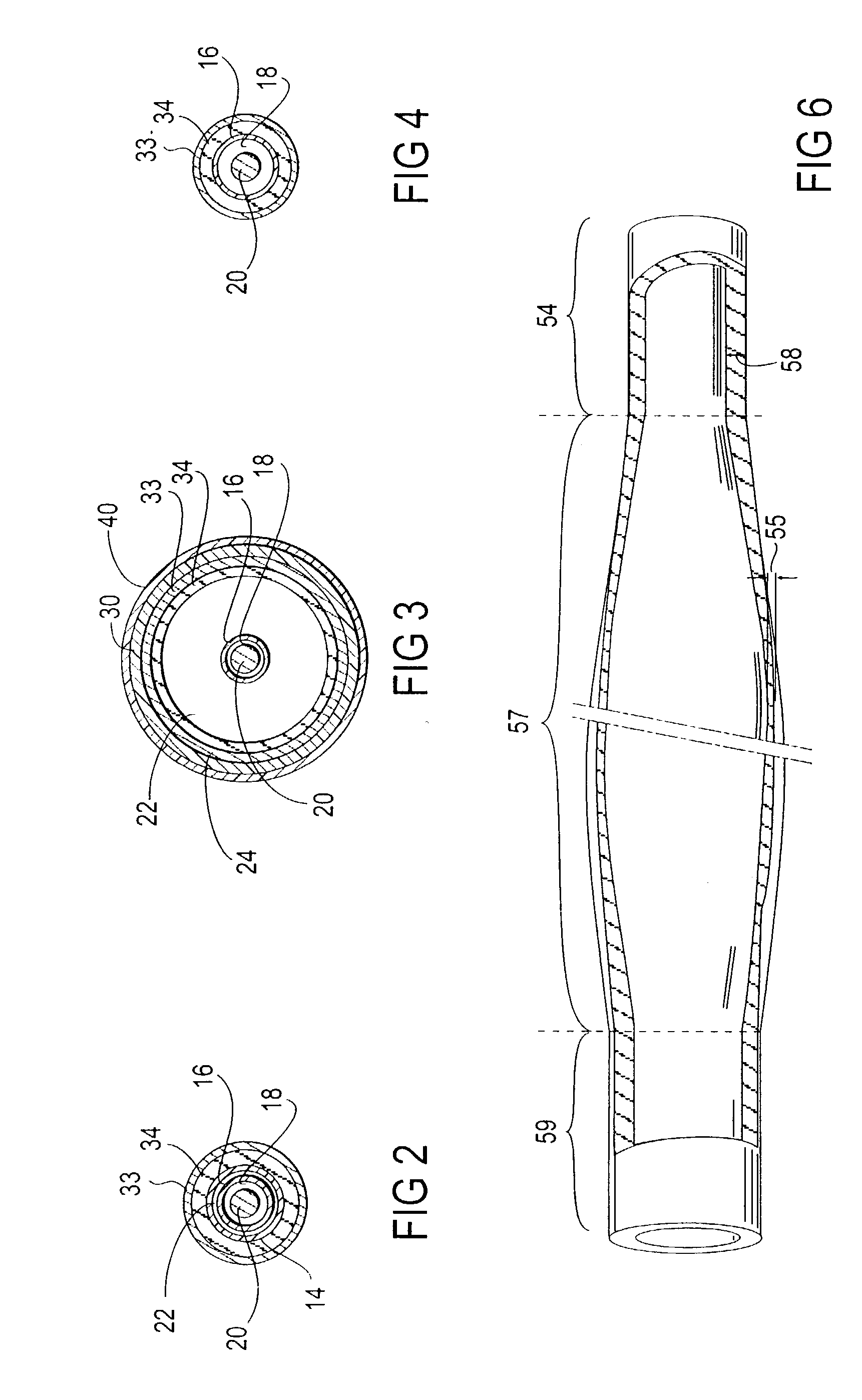
[0026]FIG. 1 illustrates an over the wire type stent delivery balloon catheter 10 embodying features of the invention. Catheter 10 generally comprises an elongated catheter shaft 12 having an outer tubular member 14 and an inner tubular member 16. Inner tubular member 16 defines a guidewire lumen 18 configured to slidingly receive a guidewire 20, and the coaxial relationship between outer tubular member 14 and inner tubular member 16 defines annular inflation lumen 22, as best shown in FIG. 2 illustrating a transverse cross section view of the distal end of the catheter shown in FIG. 1, taken along line 22. An inflatable balloon 24 disposed on a distal section of catheter shaft 12 has a proximal skirt section 25 sealingly secured to the distal end of outer tubular member 14 and a distal skirt section 26 sealingly secured to the distal end of inner tubular member 16, so that its interior is in fluid communication with inflation lumen 22. An adapter 36 at the proximal end of catheter ...


PUM


Abstract

A method of making a catheter balloon, and a balloon catheter formed thereby, in which a layer of a catheter balloon is formed by providing a tubular member to serve as a non porous liner for cooperation with a polymeric tube, and enlarging radially a central or working section of the tubular member such that a first end of the tubular member is smaller in the radial direction with respect to the working section. The tubular member may also have a thickness at the working section that is less than a thickness of the first and second end portions. The first end section of the tubular member is bonded to a catheter shaft having a first outer diameter to form at least a portion of a skirt section of the balloon, and the second end section is bonded to the catheter shaft having a second outer diameter to form a portion of a skirt section, where the skirt sections have an improved high rupture pressure.

Description

BACKGROUND OF THE INVENTION[0001]This invention generally relates to catheters, and particularly intravascular catheters for use in percutaneous transluminal coronary angioplasty (PTCA) or for the delivery of stents.[0002]In percutaneous transluminal coronary angioplasty (PTCA) procedures a guiding catheter is advanced in the patient's vasculature until the distal tip of the guiding catheter is seated in the ostium of a desired coronary artery. A guidewire is first advanced out of the distal end of the guiding catheter into the patient's coronary artery until the distal end of the guidewire crosses a lesion to be dilated. A dilatation catheter, having an inflatable balloon on the distal portion thereof, is advanced into the patient's coronary anatomy over the previously introduced guidewire until the balloon of the dilatation catheter is properly positioned across the lesion. Once properly positioned, the dilatation balloon is inflated with inflation fluid one or more times to a pre...

Claims


Application Information

Patent Timeline
IPC IPC(8): A61M29/00A61M25/00
CPCA61M25/1029A61M2025/1075A61M25/1034
Inventor LIM, FLORENCIAWANG, EDWIN
Owner ABBOTT CARDIOVASCULAR
Why Eureka
Try Eureka