Pillow

a technology of pillow and backrest, applied in the field of pillow, can solve the problems of sprained neck, neck pain, neck strain, etc., and achieve the effects of reducing the weight of the pillow, preventing the strain of the upper and lower connecting members, and increasing the rigidity of the connecting members

Inactive Publication Date: 2007-05-31
NAKAYAMA SHINICHIRO
View PDF3 Cites 22 Cited by
  • Summary
  • Abstract
  • Description
  • Claims
  • Application Information

AI Technical Summary

Benefits of technology

[0008] Yet another object of the present invention is to provide a pillow in which no unnecessary force is required to maintain the height of the back of the head sufficiently low when the user places his / her head on the head placement member in a face-up lying position, so as to prevent load from being applied on the neck.
[0061] The sixth difference between the pillow 1 of the second embodiment and that of the first embodiment is that on a ceiling surface of the hollow portion 8 of the head placement member 3 is laminated a backing panel 32 made of an elastic member, such as a rubber foam, which is harder than the low repulsion urethane foam comprising the head placement member 3. If the head placement member 3 is formed of a molded member made of low repulsion urethane foam, when the user takes a side lying position or a face-down lying position so that his / her face is in contact with the head placement member 3, the existence of components of the biasing mechanism 9 in the hollow portion 8 such as the link members 12 and 13 or the upper connecting members 18 and 20 are noticed through the head placement member 3, which makes the user unpleasant. By providing a backing panel 32 mentioned above, the user will not easily feel the existence of components of the biasing mechanism 9, and thus, it becomes possible to prevent the user from feeling unpleasant. Further, since the link members 12 and 13 or the upper connecting members 18 and 20 are not disposed at the area corresponding to the center portion of the ceiling surface of the hollow portion 8 of the head placement member 3, it becomes possible to form the backing panel 32 to have a rectangular annular shape and to not have the backing panel 32 laminated on the center portion of the ceiling surface.

Problems solved by technology

However, there is a drawback in that in order to maintain the head placement member to an elevated position corresponding to the head of the user taking a side lying position resisting against the load of the head, it is necessary to set the upward biasing force at the elevated position of the head placement member to correspond to the load of the head, so that even if the user takes a face-uplying position, the head placement member will not descend responsively, and as a result, load is applied on the neck.
Furthermore, there is another drawback according to the prior art pillow mentioned above in that the head placement member is not designed to be depressed by the load of the head, and even when the head placement member is at its most descended position in which the link members of the X-shaped link are folded horizontally, a space corresponding to the width of the link members in the upward / downward direction is formed between the head placement member and the bottom member, so that when the user places his / her head on the head placement member in a face-up lying position, the position of the back of the head is not located at a sufficiently low position.
Yet another drawback of the prior art pillow is that since the head placement member is constantly subjected to biasing force in the upward direction, the user must constantly resist against the biasing force in order to maintain the position of the head low, by which load is applied to the neck, causing problems such as stiff shoulders, headache, numbness in the hands and legs, neck pain, sprained neck, and so on.

Method used


Image

  • Pillow
  • Pillow
  • Pillow

Examples


first embodiment

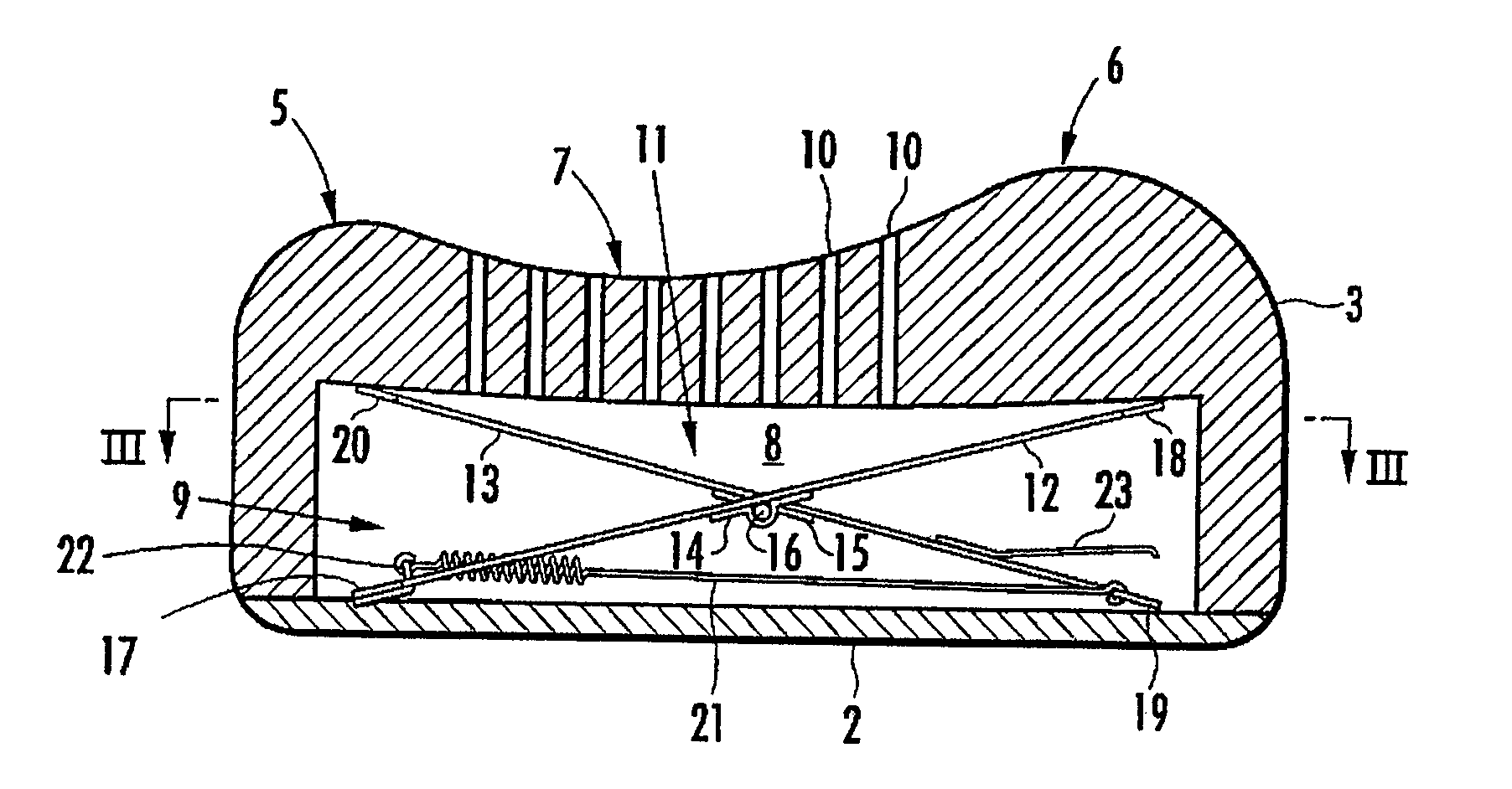
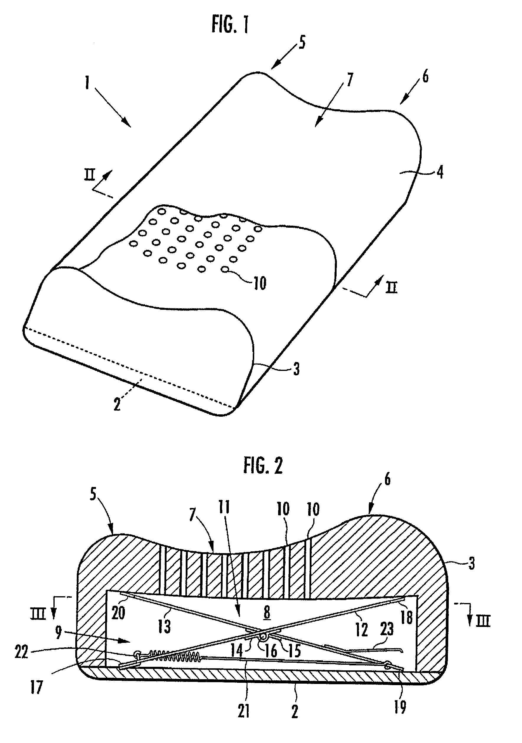
[0030] As shown in FIG. 1, the pillow 1 according to the invention comprises a bottom member 2 formed of felt or the like and a head placement member 3 disposed above the bottom member 2, wherein the bottom member 2 and the head placement member 3 are covered with an outer cover fabric 4. The head placement member 3 is formed of a molded member made of low repulsion urethane, and is designed so that the planar shape has a horizontally long, substantially rectangular shape. With a head of a user placed on the head placement member 3, if the side corresponding to the crown portion of the head is called a rear side and the side corresponding to the neck is called a front side, there is a lower ridge portion 5 formed on the rear side and a higher ridge portion 6 formed on the front side of the upper portion of the heat placement member 3, and a saddle portion 7 is formed in the area between both ridges 5 and 6.

[0031] The head placement member 3 has a hollow portion 8 formed in the inter...

second embodiment

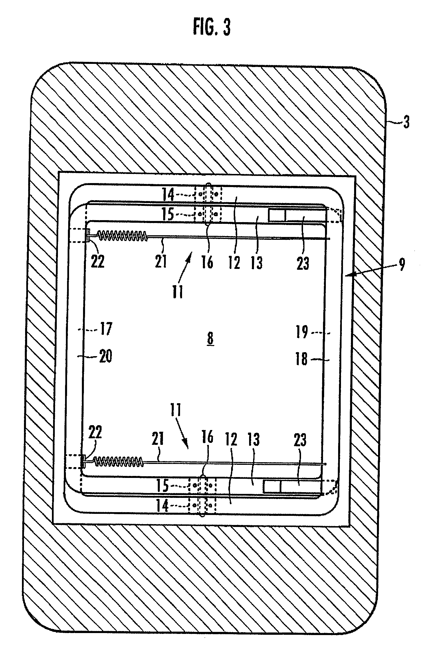
[0051] When the head placement member 3 is in a non-depressed condition, the X-shaped links 11 are biased to the expanding direction by the resultant force of the biasing force of the upper tension springs 26 and the biasing force of the lower tension springs 27, so that the necessary biasing force in the expanding direction required to maintain the head placement member 3 in the non-depressed condition can be obtained even if the spring forces of the upper and lower tension springs 26 and 27 are relatively small. As a result, even if the rigidity of the upper connecting members 18 and 20 and the lower connecting members 17 and 19 are not especially high, the connecting members 17 through 20 can be prevented from being deflected by the spring force, so the weight of the connecting members 17 through 20 can be reduced, and as a result, the weight of the pillow 1 can be reduced. Further, the upper tension springs 26 are the spring member serving to reverse the vertical positional rel...


PUM


Abstract

The invention provides a pillow capable of having the height thereof adjusted automatically so that the height of the back of the head of a user in a face-up lying position is slightly higher than his / her back, and also capable of having the height thereof varied automatically between a face-up lying position and a side lying position. A hollow portion 8 having a biasing mechanism 9 disposed therein is formed in a head placement member 3, and when the head is placed face-up on the head placement member 3, the hollow portion 8 is depressed so that the distance between the lowermost portion of the head and the bottom member 2 is in the range of 10 mm to 30 mm. The biasing mechanism has X-shaped links 11 disposed laterally spaced apart in the hollow portion 8. Each X-shaped link is composed by pivotally connecting a first link member 12 slanted upward toward the front and a second link member 13 slanted upward toward the rear by an intermediate link shaft 16. The biasing mechanism further comprises a front-side upper connecting member 18 for connecting the front ends of the first link members of the X-shaped links, a rear-side upper connecting member 20 for connecting the rear ends of the second link members of the X-shaped links, and a spring member 21 providing a spring force for approximating the link members of each X-shaped link in the frontward / rearward direction along a line of action in the frontward / rearward direction with respect to the X-shaped links.

Description

TECHICAL FIELD [0001] The present invention relates to a pillow used as bed clothes, and more specifically, to a pillow capable of having its height varied according to the user's sleeping position. BACKGROUND ART [0002] The most natural and preferable position of a person during sleep is a position in which an upright position is brought down as it is to a face-up lying position. In this state, the back of the head which is the lowest position of the head is placed slightly higher than the back, but the rear side surface of the neck is placed 10 mm to 50 mm higher than the back of the head. Therefore, when the user is taking a face-up lying position, the pillow used as bedclothes should desirably maintain the position of the back of the head to be slightly higher than the back while supporting the neck which is placed higher than the back of the head with appropriate strength. [0003] On the other hand, when the user rolls over during sleep and takes a side lying position, the head ...

Claims


Application Information

Patent Timeline
Patent Type & Authority Applications(United States)
IPC IPC(8): A47G9/00
CPCA47G9/1009A47G2009/1018A47G9/109A47G9/10
Inventor NAKAYAMA, SHINICHIRO
Owner NAKAYAMA SHINICHIRO
Why Eureka
Try Eureka