
Fishing hook and method for attaching a snell to a fishing hook

Inactive Publication Date: 2007-05-31
GRUBER JEFF A
View PDF17 Cites 24 Cited by
  • Summary
  • Abstract
  • Description
  • Claims
  • Application Information

AI Technical Summary

Benefits of technology

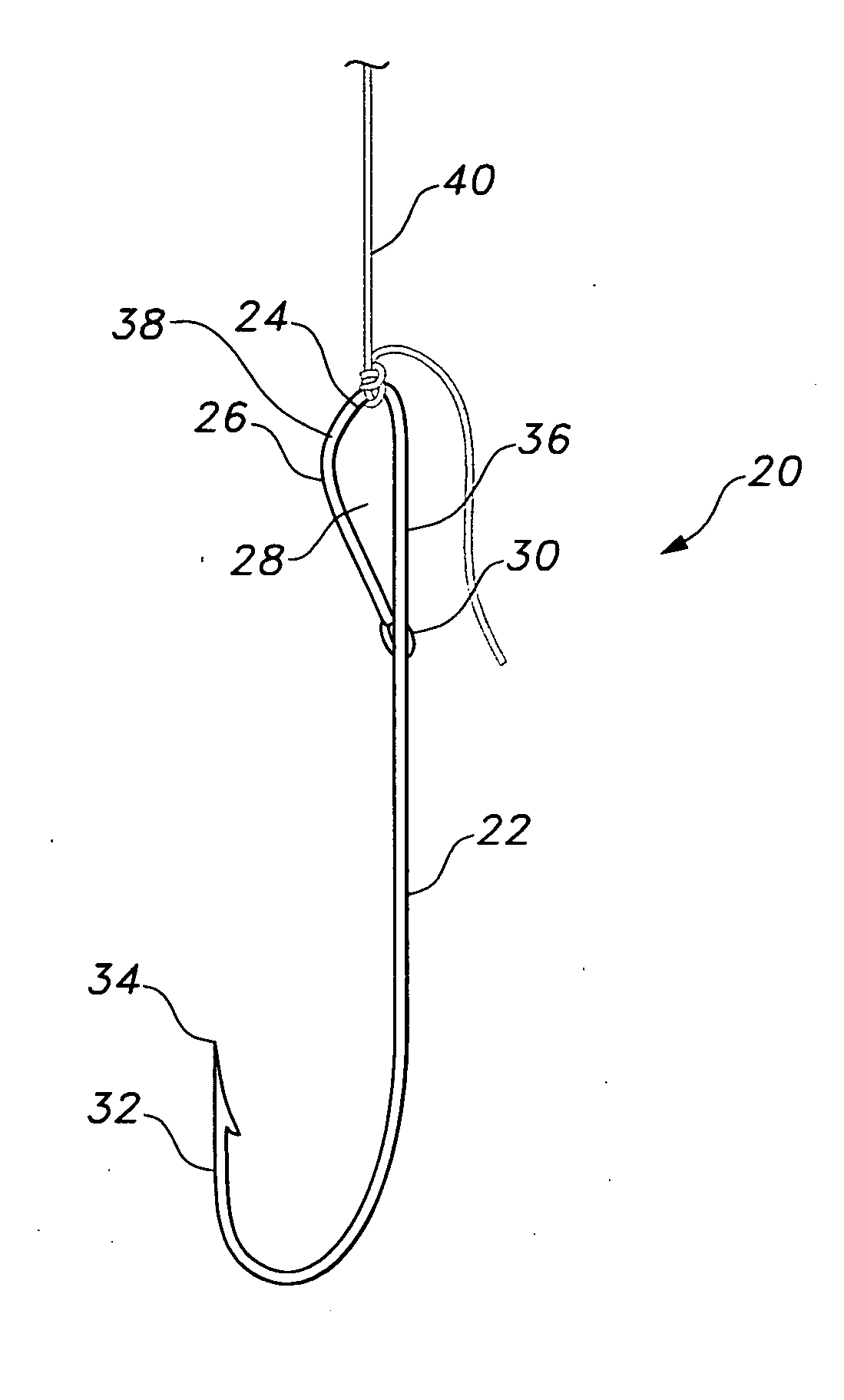
[0013] The fishing hook and method for attaching the snell allows for relatively fast and easy placement of one or more of such fishing hooks on a fishing line, and allows for easy visual identification, by a fisherman or the like, of the position of the hook point within the mouth of a hooked fish. As will be described in further detail below, the present invention includes a hook point indicator, allowing the fisherman to easily discern the position of the hook point with respect to the eyelet; i.e., the hook point indicator allows the fisherman to determine the direction of the bend at the bottom of the hook with respect to the eyelet.

Problems solved by technology

Fishermen using conventional hook designs encounter a number of problems.
The first problem is the issue of securing a fishing line or a leader line to the hook.
A number of knots for securing the line to conventional fish eyelets are known, but many conventional knots are difficult to tie properly, particularly when the user is wearing gloves, or if the user's manual dexterity is impaired from exposure to the cold weather which users often find conducive to catching fish.
Improperly tied knots can result in the line becoming detached from the hook, causing a loss of the fishing tackle, attached bait, or even a fish escaping after being hooked.
Another issue with conventional hooks involves hazards presented when attempting to remove a fish from the hook once the fish is caught.
When a user attempts to grip the eyelet of a hook to free a live fish, the movements of the struggling fish may cause the sharp edge from the hook to cut into the hands and fingers of the user.
Further, conventional fishing hooks are often difficult to extract from a fish's mouth because the fish may swallow the hook, thus leaving only a small upper portion of the eyelet for the user to grasp while attempting to pull and work the hook free from the fish.
The result is that the line of force along the fishing line may deviate from the line of action of the hook portion of the fishing hook, eliminating the desired lever action and increasing the risk that the fish may escape.

Method used


Image

  • Fishing hook and method for attaching a snell to a fishing hook
  • Fishing hook and method for attaching a snell to a fishing hook
  • Fishing hook and method for attaching a snell to a fishing hook

Examples


Embodiment Construction

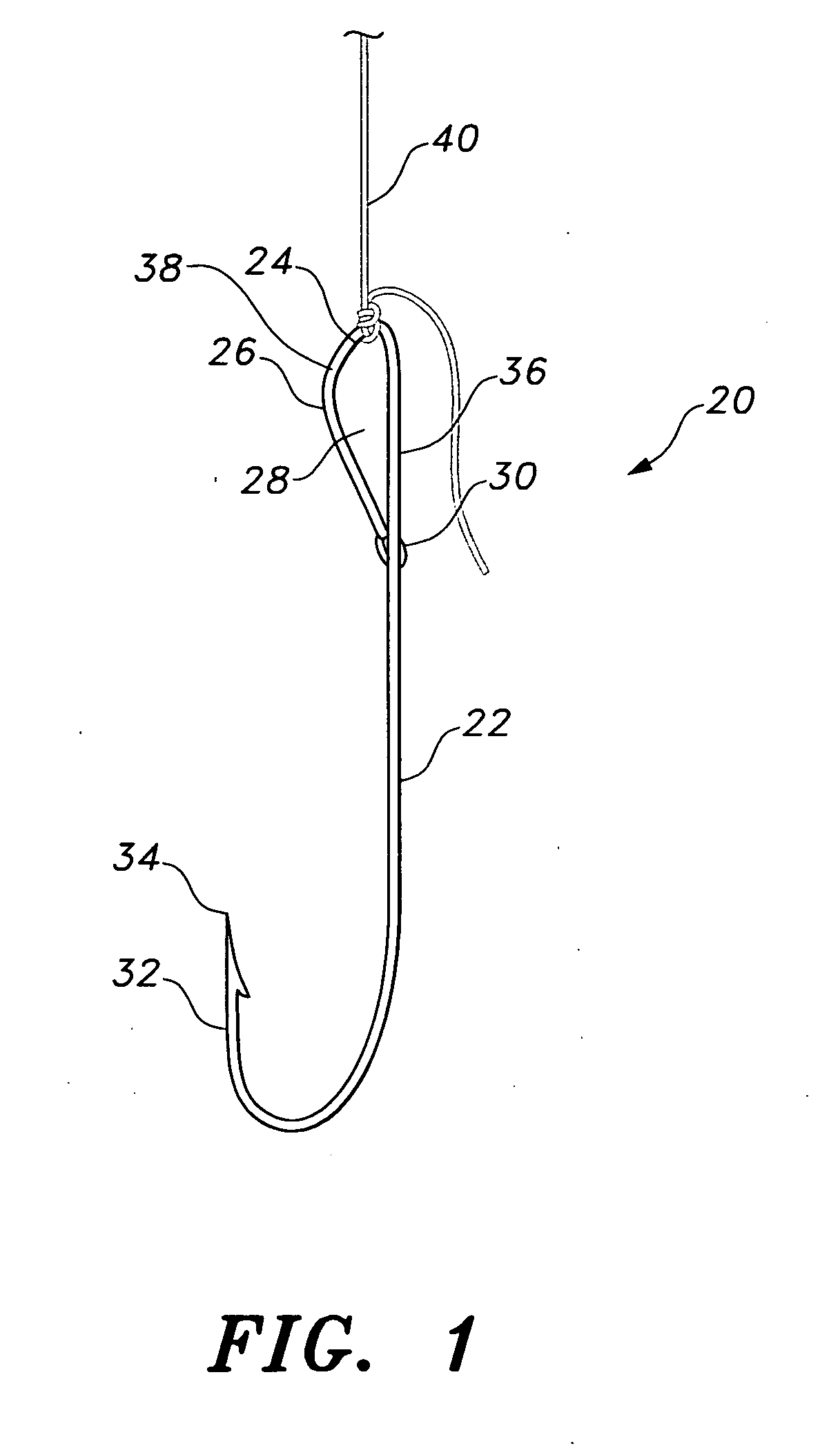
[0029] The present invention is a fishing hook and a method for attaching a snell a line to the fishing hook. Referring first to FIG. 1, features of the fishing hook may be appreciated.

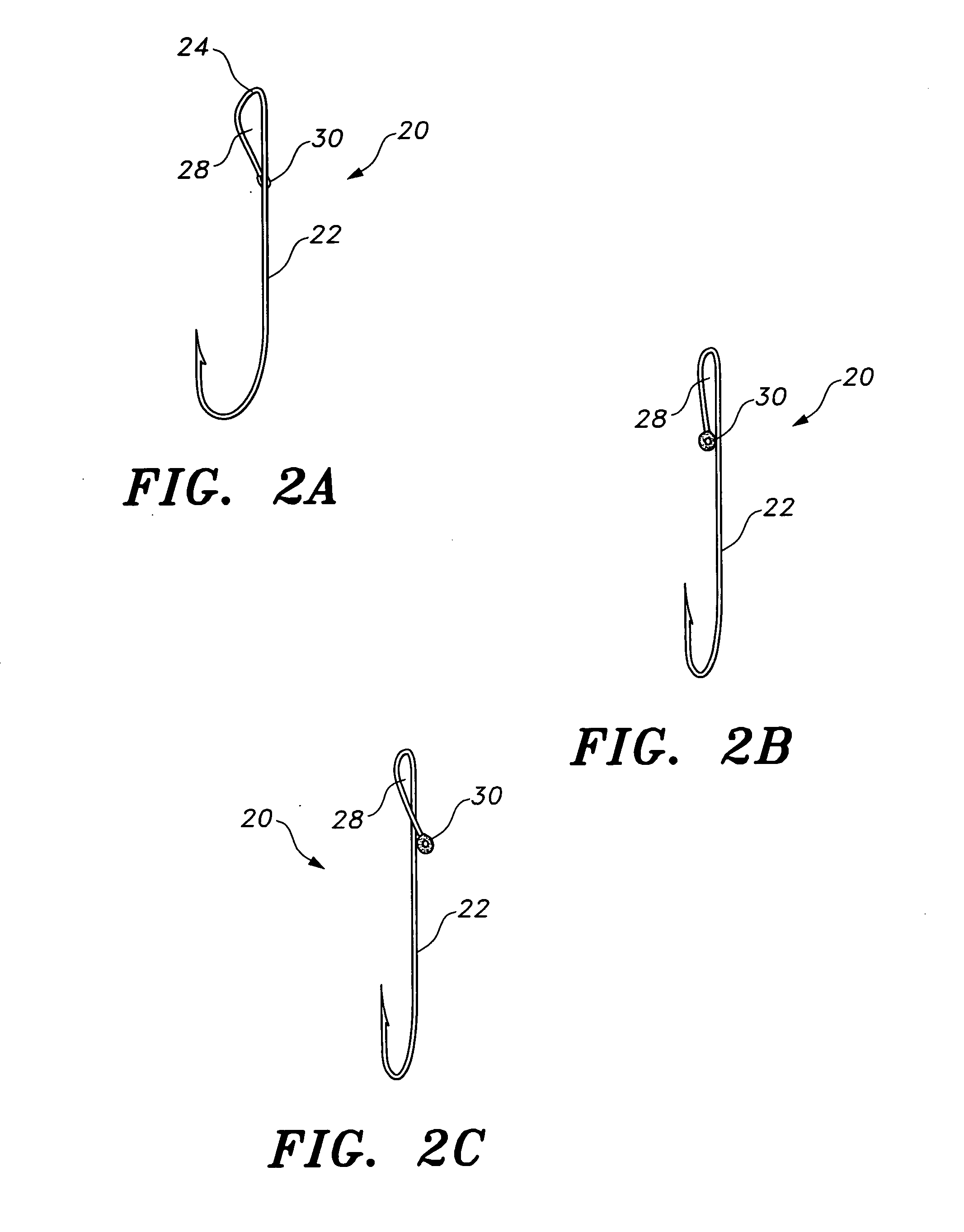
[0030] The fishing hook 20 is preferably formed from a relatively strong metal wire. The fishing hook 20 includes a shank 22. The lower end of the shank 22 is bent to form a hook portion 32 that comes to a barbed point 34. The upper portion of the shank 22 is preferably bent to form a D-shaped eyelet 26 defining an eyelet opening 28 with a cleft 24 (best shown in FIG. 2A) at the apex of the eyelet 26. The D-shaped eyelet 26 is formed by a rectilinear extension 36 of the shank and an arcuate leg 38 that curves downward and outward from the apex of the eyelet 26 towards the point 34 of the hook portion 32 and then back towards the shank 22. A leader line or snell 40 is attached to the fishing hook 20 with a knot that lodges in the cleft 24 of the eyelet 26. The cleft 24 maintains the position of the kn...


PUM


Abstract

The fishing hook has a shank, a pointed hook portion formed at the lower end of the shank, and an eyelet formed at the upper end of the shank. The eyelet is formed by a generally D-shaped open loop that defines a cleft at the apex of the eyelet. The method of attaching a snell (a short leader line) to a fishing hook includes the steps of: forming a loop in a snell; passing the loop through the eyelet; rotating the fishing hook at least one full rotation to twist the loop; passing the loop over the open end of the eyelet; and pulling the snell to form a knot at the apex of the eyelet.

Description

CROSS-REFERENCE TO RELATED APPLICATION [0001] This application claims the benefit of U.S. Provisional Patent Application Ser. No. 60 / 740,269, filed Nov. 29, 2005.BACKGROUND OF THE INVENTION [0002] 1. Field of the Invention [0003] The present invention relates to equipment for catching fish, and more particularly to fishing hooks. [0004] 2. Description of the Related Art [0005] Fishing hooks typically consist of a shank with a hook extending from the lower portion of the shank. An eyelet is provided at the upper end of the shank for attaching a fishing line to the hook. [0006] Fishermen using conventional hook designs encounter a number of problems. The first problem is the issue of securing a fishing line or a leader line to the hook. It is important that the line be firmly secured to the hook so that a fish, once hooked, does not escape by pulling the hook free from the line. A number of knots for securing the line to conventional fish eyelets are known, but many conventional knots...

Claims


Application Information

Patent Timeline
IPC IPC(8): A01K83/00
CPCA01K83/00A01K91/04A01K97/18
Inventor GRUBER, JEFF A.
Owner GRUBER JEFF A
Learn More