
Object feeder system

a feeder system and object technology, applied in the field of object feeder systems, can solve the problems of affecting the modeling of implants and shells, affecting the accuracy of scanning, so as to facilitate the establishment of contact with the object holder

Active Publication Date: 2016-05-03
3SHAPE AS
View PDF10 Cites 0 Cited by
  • Summary
  • Abstract
  • Description
  • Claims
  • Application Information

AI Technical Summary

Benefits of technology

The patent describes a plate assembly that can hold multiple object holders in a scanner. This makes it easy to quickly place each object in a holder and then scan them quickly. The plate assembly can also be placed in a three-dimensional analyzing device, where it can be positioned to provide the best analysis or recording of each object based on its unique design.

Problems solved by technology

For hearing aid shells sub-millimeter precision is required or the shell will cause irritation, acoustic feedback and possibly infection to the epidermis of the ear canal.
Therefore systematic or random errors in the calibration and / or performance of scanners for these uses can be critical.
This has hitherto limited the use of scanning in the modeling of such implants and shells.
It remains a problem to provide an object feeder where the objects can be scanned easily, effectively and reliably.
For most situations, a single scan will not produce a complete model of the object.

Method used


Image

  • Object feeder system
  • Object feeder system
  • Object feeder system

Examples


Embodiment Construction

[0196]In the following description, reference is made to the accompanying figures, which show by way of illustration how the invention may be practiced.

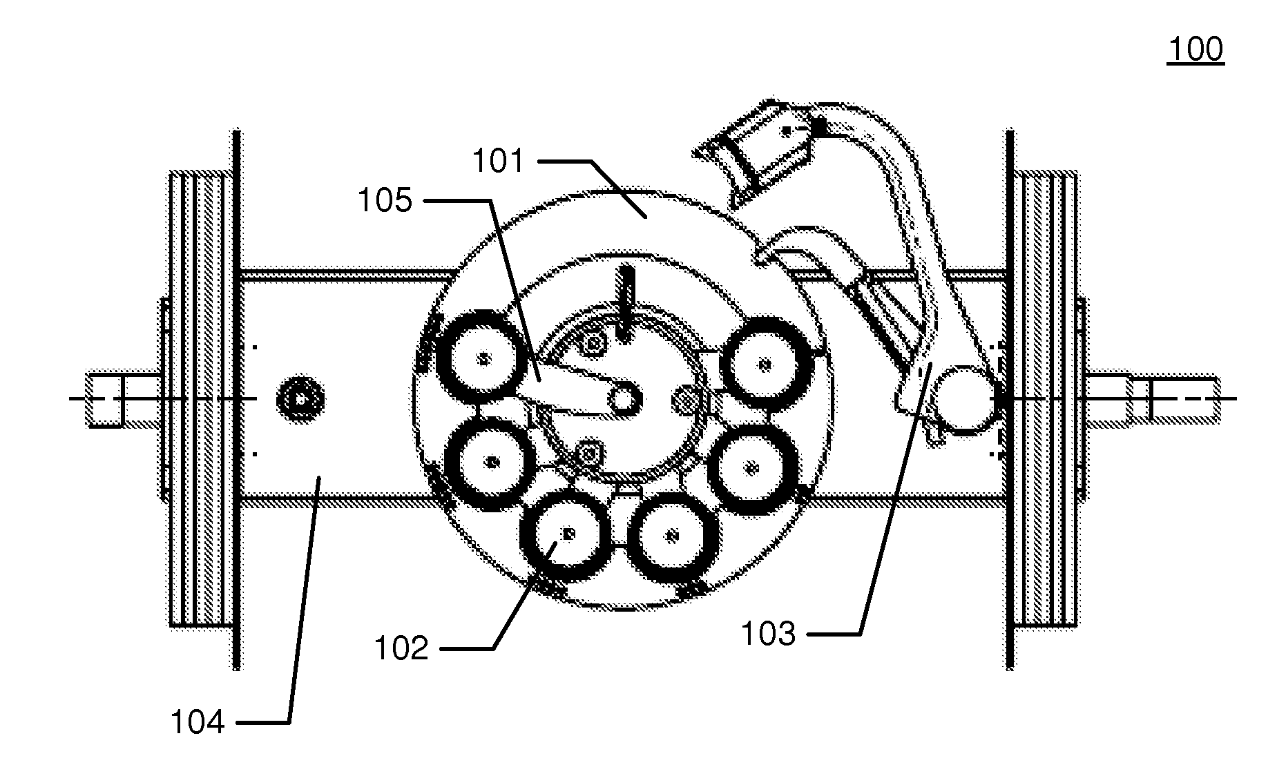
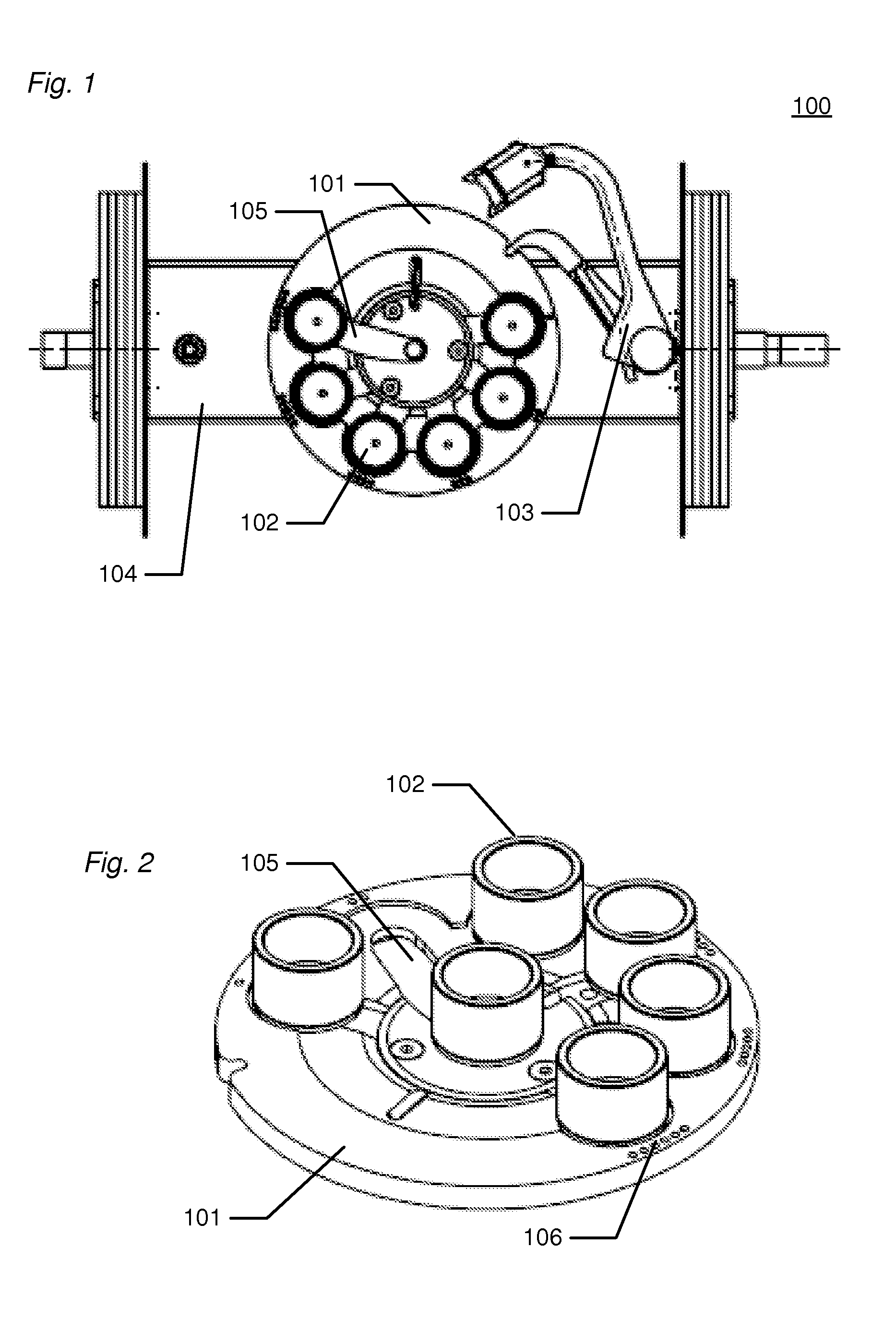
[0197]FIG. 1 shows an example of the object feeder system 100 seen from above. The object feeder system comprises a plate assembly 101 with object holders 102 mounted in tracks 105, and an arm assembly 103 for moving the object holders 102.

[0198]All object holders 102 are arranged in their respective tracks 105 in the outer edge of the plate assembly 101.

[0199]The object feeder system 100 is arranged on a swinging axis 104 in a scanner (not shown).

[0200]Due to the arrangement of the object holders 102 on the plate assembly 101 there is nothing obstructing the passage of emitted light from the light source in the scanner to an object in an object holder 102 in a scanning area in the centre of the plate assembly 101, and nothing obstructing the passage of light reflected from the object in the object holder 102 in the scanning area in ...


PUM


Abstract

Disclosed is an object feeder system configured for arrangement in a three dimensional scanner, the system comprising: an object feeder scanning plate assembly comprising a number of tracks, wherein each track adapted to hold at least one object holder, wherein said tracks are configured to extend within the plate assembly from a parking area towards a scanning area, and where each object holder is configured for retaining an object to be scanned in the scanner for obtaining a three dimensional representation of the object, and wherein the object feeder system further comprises means for moving the at least one object holder in the at least one track.

Description

FIELD OF THE INVENTION[0001]This invention generally relates to an object feeder system adapted to be arranged in a three dimensional (3D) scanner. More particularly, the invention relates to an object feeder scanning plate assembly comprising at least one track adapted to hold at least one object holder, where the at least one object holder is configured for retaining an object to be scanned in the scanner for obtaining a three dimensional representation of the object. The three dimensional representation of the object may comprise the surface of the object.BACKGROUND OF THE INVENTION[0002]Systems for three-dimensional optical scanning are well known in the prior art. They typically comprise one or more light sources projecting a structured light pattern on the object to be scanned, one or more cameras and data processing equipment to convert the recorded image co-ordinates to three dimensional co-ordinates using state of the art software. Usually, only a part of the object is scan...

Claims


Application Information

Patent Timeline
Patent Type & Authority Patents(United States)
IPC IPC(8): B65G47/86B65G47/84G01B5/00
CPCB65G47/846B65G47/847G01B5/0002
Inventor CLAUSEN, TAISFISKER, RUNEHOLLENBECK, KARL-JOSEFNIELSEN, CHRISTIAN HOJRISSTEGMANN, MIKKEL BILLESCHRODER, MORTEN RUDKJ.AE BUTTED.RJENSEN, SOREN GREVEPETERSEN, BO
Owner 3SHAPE AS
Learn More