Flow channel switching valve and shower system

a channel switching valve and shower system technology, applied in the direction of valves, mechanical devices, engine components, etc., can solve the problems of shower system large installation space, shower head water having an improper temperature, and inability to install the shower system

Inactive Publication Date: 2007-05-31
KITAMURAGOKIN IND
View PDF4 Cites 24 Cited by
  • Summary
  • Abstract
  • Description
  • Claims
  • Application Information

AI Technical Summary

Benefits of technology

[0009] It is a purpose of the present invention to provide a more compact channel switching valve which can drain not only fluid having a proper temperature, but also fluid having an improper temperature as required through a drain port for draining fluid having proper temperature. It is also a purpose of the present invention to provide a shower system comprising such a channel switching valve.

Problems solved by technology

However, in the above described channel switching valve, the user cannot intentionally cause water having an improper temperature to be drained from the shower head.
Therefore, this shower system is relatively large and requires a large installation space.
Thus, if the space in a bath is small, the shower system cannot be installed.

Method used


Image

  • Flow channel switching valve and shower system
  • Flow channel switching valve and shower system
  • Flow channel switching valve and shower system

Examples


Embodiment Construction

[0028] Now, a first embodiment of the present invention will be described with reference to the drawings.

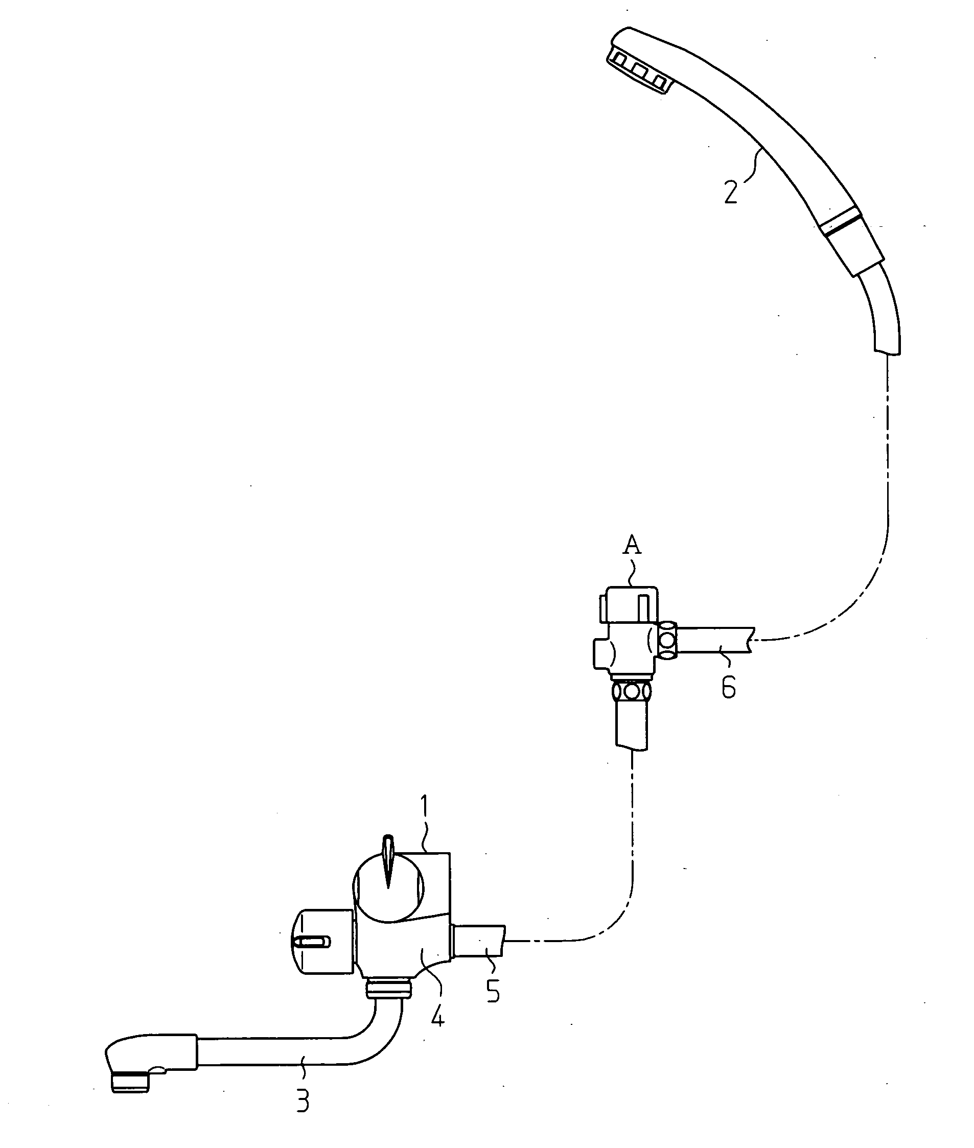
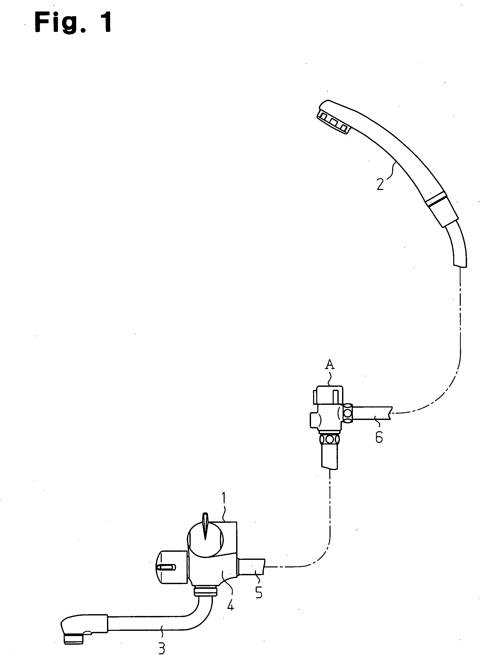
[0029] As shown in FIG. 1, a channel switching valve A according to this embodiment is attached between a combination faucet 1 and a shower head 2 in a bathroom, for example. A supply tube 5 is connected to the combination faucet 1 which adjusts temperature and flow rate of water which is a fluid. The combination faucet 1 comprises a switching valve 4 such that the water, which is adjusted in temperature and flow rate, is selectively supplied to either the supply tube 5 or a water discharge tube 3 of the combination faucet 1 by operating the switching valve 4. The supply tube 5 is linked to a hose 6 through the channel switching valve A. The shower head 2 is attached at a tip of the hose 6. The channel switching valve A, the shower head 2 and the hose 6 constitute a shower system.

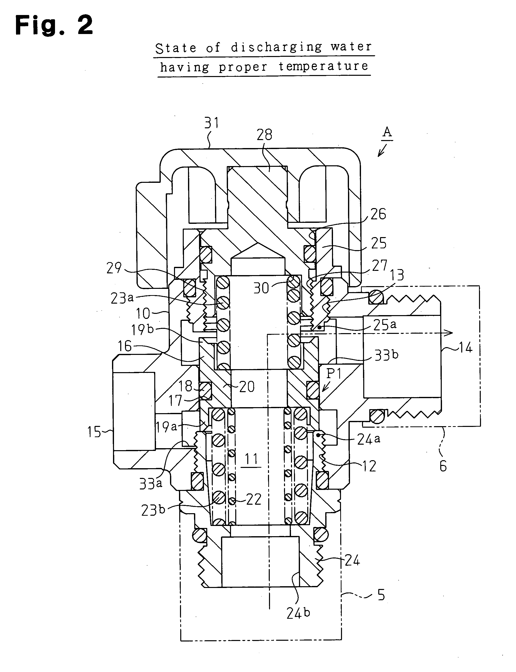
[0030] As shown in FIG. 2, the channel switching valve A comprises a hollow body 10. A first openin...


PUM


Abstract

A channel switching valve (A) of the present invention includes a discharge hole (14) which discharges water having a proper temperature and a drain hole (15) which drains water having an improper temperature. A part of a first channel (11) extending from a hot water supply port (24b) to the discharge hole and a part of a second channel (11) extending from the hot water supply port to the drain hole are common. Therefore, the channel switching valve can be compact.

Description

TECHNICAL FIELD [0001] The present invention relates to a channel switching valve and a shower system. BACKGROUND ART [0002] Conventionally, as a channel switching valve, an arrangement disclosed in Patent Document 1 is known, for example. The channel switching valve comprises a temperature sensitive spring which reversibly changes its shape depending on the temperature of fluid flowing into the inside of the channel switching valve and a valve body which is biased by the temperature sensitive spring. When load is applied to the valve body with change in shape of the temperature sensitive spring, the valve body moves to switch between a state in which a drain port for fluid having a proper temperature, which is fluid having a temperature in a predetermined temperature range, is linked to the channel and a state in which a drain port for fluid having an improper temperature, which is fluid having a temperature out of a predetermined temperature range, is linked to the channel. [0003]...

Claims


Application Information

Patent Timeline
Patent Type & Authority Applications(United States)
IPC IPC(8): B05B9/01B05B9/08B05B7/02A47K3/28E03C1/02E03C1/044F16K3/24F16K31/68F16K31/70
CPCE03C1/023E03C1/044E03C2201/30
Inventor NAGANO, FUSAYUKISHINDO, TAKAHIKOKANOU, SHINOBU
Owner KITAMURAGOKIN IND
Why Eureka
Try Eureka