Magnetic position sensor for a mobile object with limited linear travel

a magnetic position sensor and linear travel technology, applied in the field of nocontact magnetic sensors, can solve the problems of limiting the application, affecting the accuracy of measurement, and affecting the accuracy of measurement, and achieves the effect of small size, simple design, and relatively large linear range of magnetic flux variation

Inactive Publication Date: 2007-05-31
ELECTRICFIL AUTOMOTIVE
View PDF1 Cites 18 Cited by
  • Summary
  • Abstract
  • Description
  • Claims
  • Application Information

AI Technical Summary

Benefits of technology

[0006] The subject of this present invention therefore aims to remedy the aforementioned drawbacks, by proposing a no-contact magnetic sensor, designed to determine the position of a mobile object moving along a limited linear distance, and that is of simple design, economic, small in size and able to operate at zero gauss, with a linear range of variation of the magnetic flux that is relatively large.

Problems solved by technology

For example, we are thus familiar with a sensor of the optical type whose major drawback concerns its cost of production.
By virtue of its design, a sensor of eddy-current or of the coil type is very bulky, and this limits its applications.
This type of magnetic sensor has the disadvantage of not being able to effect detection at a magnetic flux value of zero gauss, which leads to errors in the measurements effected.
In addition, it turns out that such a magnetic sensor has a non-linear response, with a small dynamic range, with the consequent adverse impact on its detection quality.

Method used


Image

  • Magnetic position sensor for a mobile object with limited linear travel
  • Magnetic position sensor for a mobile object with limited linear travel

Examples


Embodiment Construction

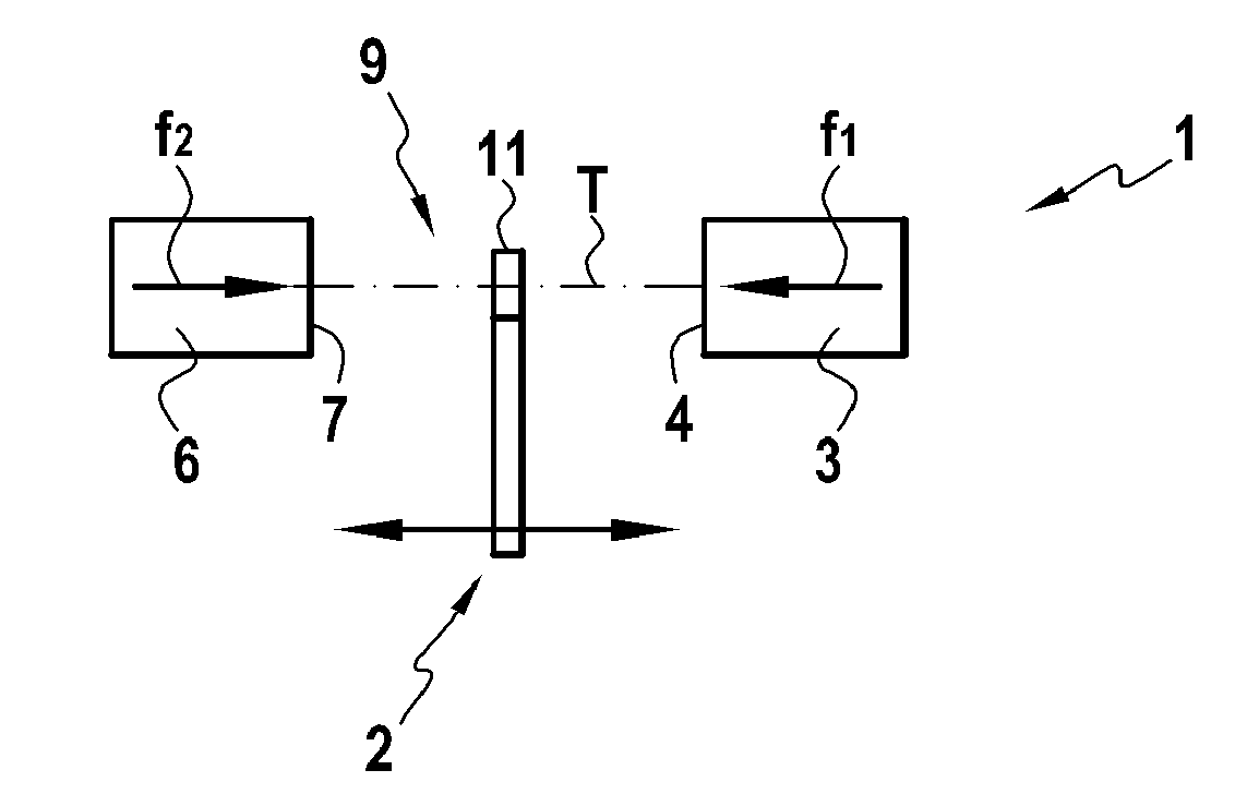
[0019] As can be seen more precisely in FIG. 1, the subject of the invention concerns a magnetic sensor 1 designed to determine the position of a mobile object 2, in the general sense, moving along an axis or a direction of motion T. The mobile object 2 represents any type of device with linear travel, forming part, preferably but not exclusively, of a device fitted to a motor vehicle, and preferably an electric braking device or arrangement in a motor vehicle.

[0020] The magnetic sensor 1 includes a first resource 3 for the creation of a magnetic field, oriented along a first axis in the direction of the axis of movement T, represented by arrow f1. In a preferred implementation variant, this first resource 3 for the creation of a magnetic field is composed of a magnet presenting a polar face 4 lying in a plane approximately perpendicular to the direction of motion T.

[0021] The sensor 1 according to the invention includes a second resource 6 for the creation of a magnetic field, or...


PUM


Abstract

A magnetic sensor including a first resource (3) for the creation of a magnetic field, oriented along a first axis in the direction of the axis of movement, and a second resource (6) for the creation of a magnetic field, oriented along a second axis in the direction of the axis of movement, opposed to the first direction. The first and second field-creation resources are mounted opposite to each other in order to form, between them, a magnetic measuring gap in which the measuring element that is sensitive to the value of the magnetic flux generated by the first and second field-creation resources is located, with the measuring element or the first and second field-creation resources being linked to the mobile object.

Description

BACKGROUND OF THE INVENTION [0001] This present invention concerns the technical area of no-contact magnetic sensors, designed to ascertain the position of a mobile object moving along a linear axis of motion. [0002] The subject of the invention finds a particularly advantageous, though not exclusive, application in the area of motor vehicles, with a view to equipping different devices with limited linear travel whose position must be known, and forming part, in particular, of an electric braking arrangement for motor vehicles. [0003] In previous designs, there are many types of no-contact sensors, designed to ascertain the linear position of a mobile object moving in translation. For example, we are thus familiar with a sensor of the optical type whose major drawback concerns its cost of production. By virtue of its design, a sensor of eddy-current or of the coil type is very bulky, and this limits its applications. [0004] We are also familiar with sensors of the magnetic type that...

Claims


Application Information

Patent Timeline
Patent Type & Authority Applications(United States)
IPC IPC(8): G01B7/14
CPCG01D5/145
Inventor DUFOUR, LAURENTLEGRAND, BERTRAND
Owner ELECTRICFIL AUTOMOTIVE
Why Eureka
Try Eureka