Supercharge Your Innovation With Domain-Expert AI Agents!

Fire hydrant locating system

Inactive Publication Date: 2007-05-31
SYNCRO +1
View PDF34 Cites 23 Cited by
  • Summary
  • Abstract
  • Description
  • Claims
  • Application Information

AI Technical Summary

Benefits of technology

[0008] The receiver, locator is powered by batteries and is designed to continuously, periodically activate the receiver on, to a wake mode, and off, to a sleep mode, during an idle condition to enable it to receive activating signals at any time from the transmitter during an emergency condition. Such periodic cycling preserves power and thereby provides an extended battery life.
[0009] The hydrant locator unit has a unique housing structure in which the receiver, locator is contained. The housing structure facilitates attachment to a fire hydrant.

Problems solved by technology

In fighting fires, time is a crucial factor and precious time is often wasted in finding a desirably located fire hydrant.
Unfortunately, the hydrants are often somewhat hidden by their surroundings such as bushes, trees, vehicles, etc.
These flags may fail in their main purpose since they too can be obscured by surroundings or be inadvertently detached.
In addition they may not be readily visible at night.
Area maps which show the location of hydrants may be of little help in some situations, including night time hours, and in addition firefighters may not be aware of the precise fire location or may be unfamiliar with the neighborhood.

Method used


Image

  • Fire hydrant locating system
  • Fire hydrant locating system
  • Fire hydrant locating system

Examples


Embodiment Construction

[0020] The following description of the preferred embodiment(s) is merely exemplary in nature and is in no way intended to limit the invention, its application, or uses.

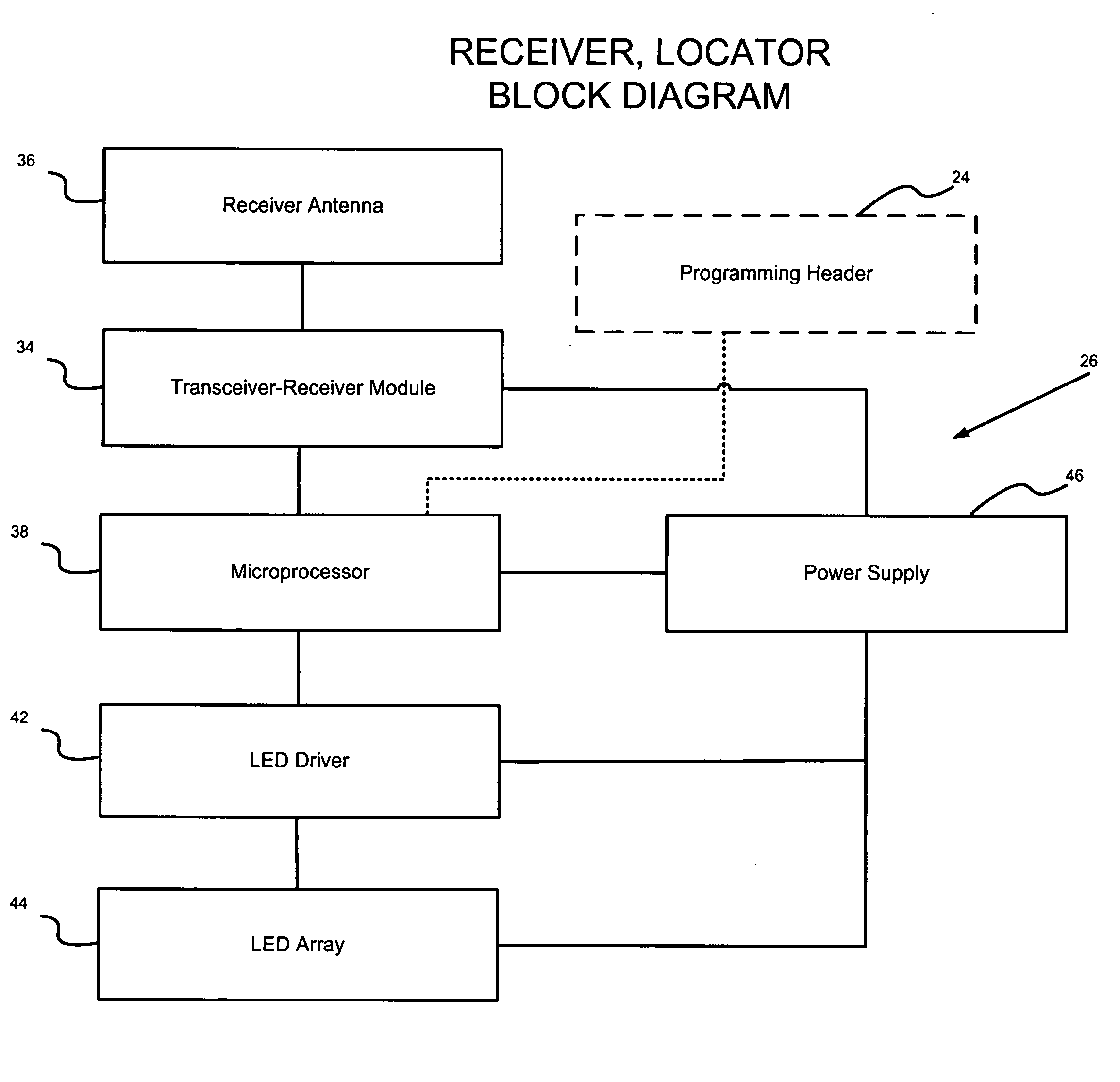
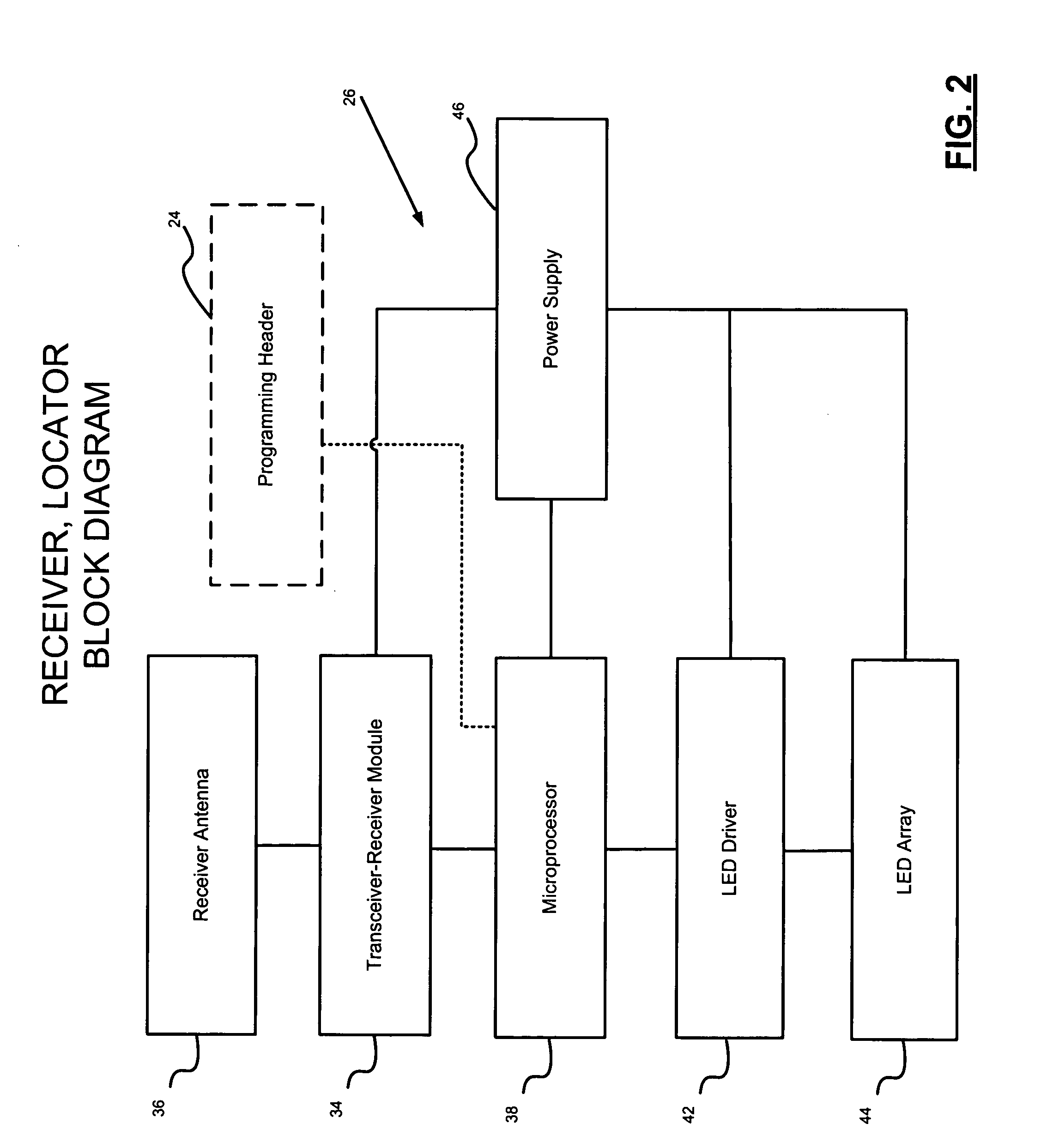
[0021] Looking now to FIG. 1, a block diagram is shown of the transmitter, actuator 10, of the fire hydrant locating system, and is adapted to be located in an emergency vehicle. Here the transmitter, actuator 10 includes an RF transceiver-transmitter module 12. In one form of the invention, the transceiver-transmitter module 12 is a transceiver which includes a transmitter section and a receiver section. However, also in one form of the invention, the transceiver-transmitter module 12 is connected only as a transmitter although it should be understood that it could also be connected as a receiver as well for different applications.

[0022] The transceiver-transmitter module 12 when actuated generates an RF signal. The output from the transceiver-transmitter module 12 is connected to an external transmitter antenna 1...


PUM


Abstract

This invention relates to a fire hydrant locating system which includes a hydrant locator that facilitates the location of a hydrant by firefighters, particularly in an emergency vehicle such as a fire engine. The hydrant locator as secured to the hydrant cylinder has a low profile. The hydrant locating system includes a transmitter adapted to be located in the emergency vehicle. Upon actuation of a switch in the transmitter in the emergency vehicle a receiver-signal generator in the hydrant locator will be activated to set off strobe lights to alert firefighters of the hydrant location. The receiver-signal generator in the hydrant locator includes a strobe light structure. The transmitter can be set such that when actuated it will activate only those hydrant locators within a preselected range such as approximately 1500 feet.

Description

FIELD OF THE INVENTION [0001] The present invention relates to a system for facilitating the remote location of fire hydrants by personnel in emergency vehicles. BACKGROUND OF THE INVENTION [0002] This invention relates to a fire hydrant locator unit that facilitates the location of a hydrant by firefighters, particularly in a fire engine (firetruck) or emergency personnel in other emergency vehicles. The hydrant locator unit as secured to the hydrant cylinder has a low profile. A selectively actuable switch in an RF (radio frequency) transmitter in an emergency vehicle will activate the transmitter to send an RF signal to an RF receiver in the hydrant locator unit to set off strobe lights in the hydrant locator to alert the firefighters or other emergency personnel of the hydrant location. [0003] In fighting fires, time is a crucial factor and precious time is often wasted in finding a desirably located fire hydrant. Ideally, firefighters want to hook up to the hydrant closest to t...

Claims


Application Information

Patent Timeline
IPC IPC(8): G08B1/08
CPCG08B21/24
Inventor BILBREY, ROBERT D.ABEL, JAMES D.CULBERT, JEFFERY S.
Owner SYNCRO
Features
  • R&D
  • Intellectual Property
  • Life Sciences
  • Materials
  • Tech Scout
  • Unparalleled Data Quality
  • Higher Quality Content
  • 60% Fewer Hallucinations
Learn More