Vehicle diagnostic system

a vehicle diagnostic and vehicle technology, applied in the field of vehicle diagnostic systems, can solve the problems of unreliability and cost, and the mechanism to judge whether or not vehicle diagnostic information is correctly transmitted to telecommunication equipment, and achieve the effect of minimizing costs and low cos

Inactive Publication Date: 2007-05-31
HITACHI LTD
View PDF10 Cites 19 Cited by
  • Summary
  • Abstract
  • Description
  • Claims
  • Application Information

AI Technical Summary

Benefits of technology

[0005] The present invention provides a vehicle diagnostic system capable of transmitting diagnostic information or signal of a vehicle to outside of the vehicle by means of radio communication like OBD III, detecting abnormality of the vehicle diagnostic system, which is caused by a failure of the vehicle diagnostic system itself or by manipulation of a vehicle operator and notifying the vehicle operator and / or a telecommunication equipment about the abnormality of the vehicle diagnostic system. In addition, the present invention provides a vehicle diagnostic system at low cost without newly adding a dedicated radio communication means for transmitting diagnostic information or signal of a vehicle to a telecommunication equipment by means of radio communication. In this way, it becomes possible to produce vehicles, which support OBD III, and the like, while minimizing costs.

Problems solved by technology

Unfortunately, either through vehicle operator's manipulation or diagnostic system failure, the diagnostic information is not always accurate.
Conventionally, a mechanism to judge whether or not vehicle diagnostic information is correctly transmitted toward a telecommunication equipment is both costly and unreliable due to the numerous components necessitated by previous systems.

Method used


Image

  • Vehicle diagnostic system
  • Vehicle diagnostic system
  • Vehicle diagnostic system

Examples


first embodiment

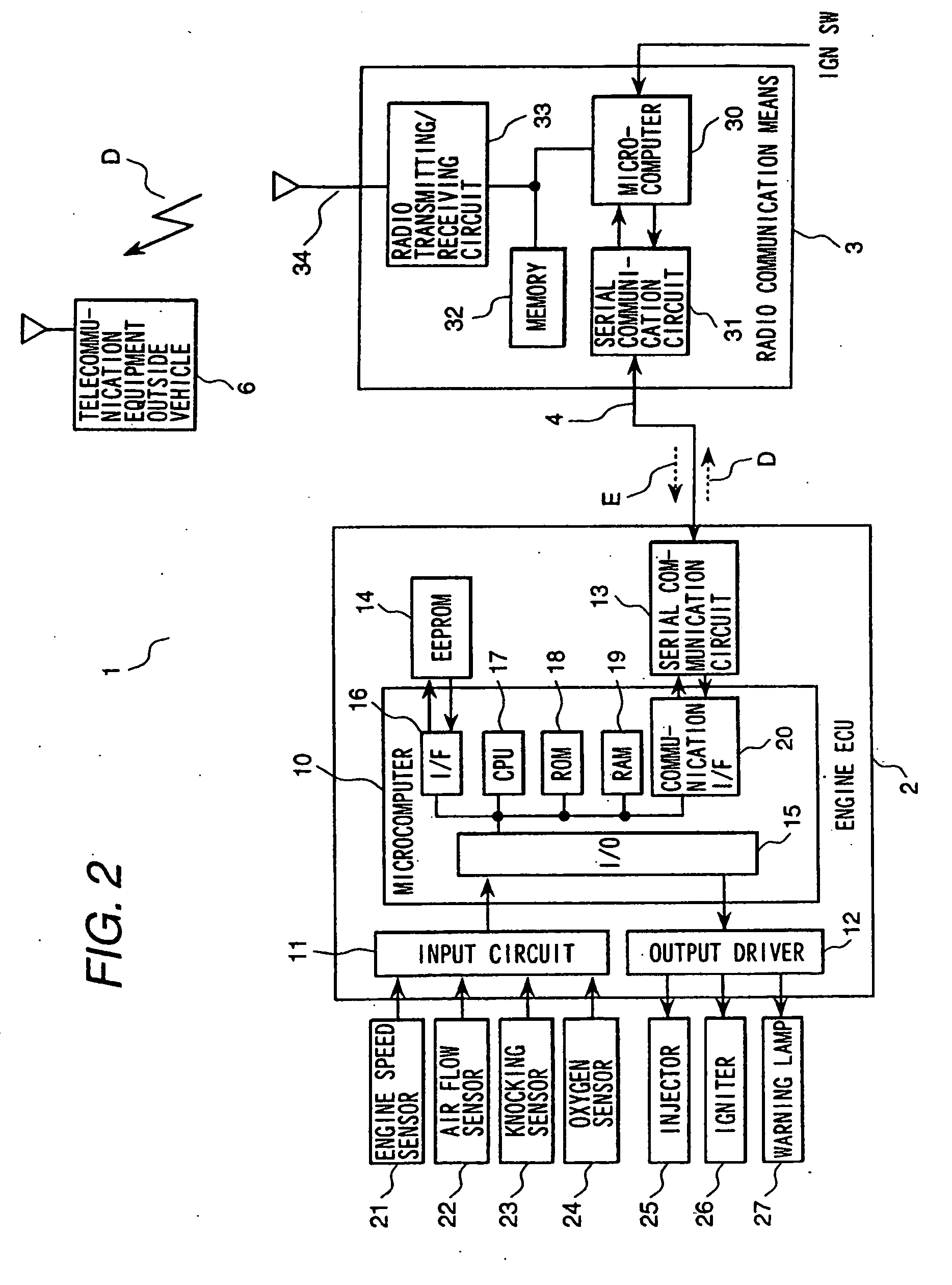
[0039] In this case, concerning a method for transmitting the vehicle diagnostic information D to the telecommunication equipment outside vehicle 6 in the event of a failure in the vehicle equipment is the same as that described in the Additionally, in this embodiment, an ignition switch (IGN SW) signal, which notifies the radio communication means 3 of ON or OFF of an ignition key, is inputted. When this ignition key becomes ON, transmitting an engine-operation enable signal E to the engine ECU 2 by the radio communication means 3 permits the engine to start. Also, the above-mentioned rolling code may be used as the engine-operation enable signal E. In this case, the engine ECU 2 compares the transmitted code with an appropriate code from among a plurality of codes stored in the EEPROM 14. As a result of the comparison, only when both codes are the same, the engine ECU 2 drives the injector 25 and the igniter 26 to start the engine.

third embodiment

[0040] Beyond the method for inputting the ignition switch (IGN SW) signal to the radio communication means 3, as shown in FIG. 3, after starting the engine, the engine ECU 2 transmits an engine-operation enable request signal EQ to the radio communication means 3 and continues the engine operation by receiving an engine-operation enable signal E from the radio communication means 3. In this case, after transmitting the engine-operation enable request signal EQ, if the engine-operation enable signal E is not returned within a predetermined period of time, the engine is stopped. In addition, transmitting an engine-operation disable signal to the engine ECU 2 by the radio communication means 3 may also disable the vehicle from traveling.

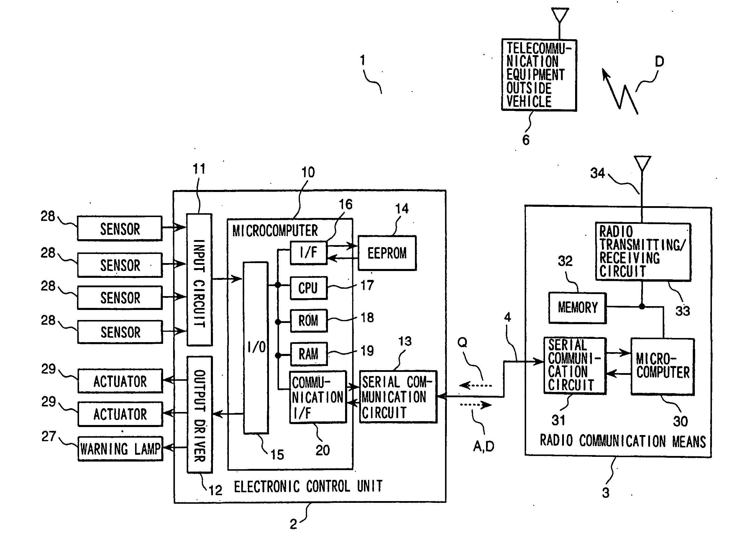
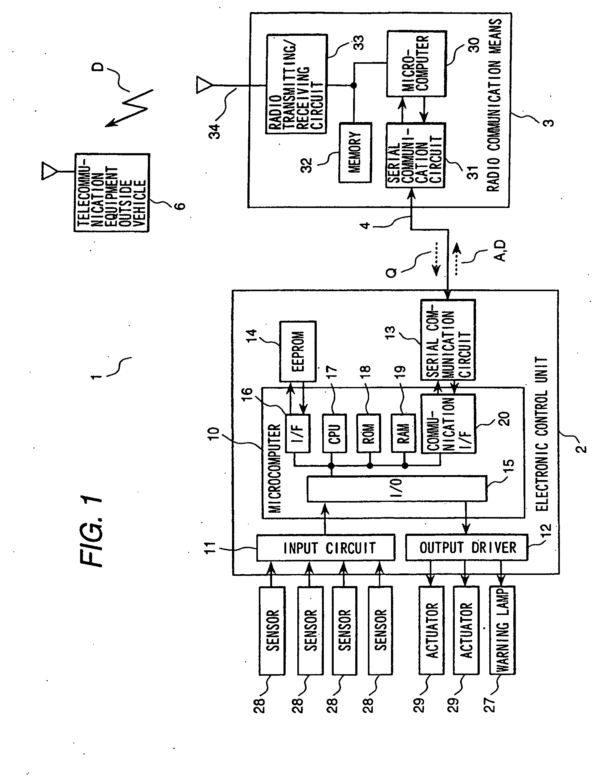
[0041] In FIG. 4, if a failure of the vehicle equipment occurs, the electronic control unit 2 stores vehicle diagnostic information D in the RAM 19, and transmits the vehicle diagnostic information D to the radio communication means 3. Then, the radio ...

fourth embodiment

[0049] Hence, according to the first and the fourth embodiment, it is possible to detect a failure or abnormality of the vehicle diagnostic system like OBD III, which transmits diagnostic information of the vehicle equipment by radio communication, by checking whether or not communication between the electronic control unit 2 and the radio communication means 3 is being performed normally, or by checking whether or not the radio communication means 3 is normal.

[0050] In addition, according to the second, the third, and the fourth embodiment, it is possible to prevent the engine from starting to disable the vehicle from traveling if the vehicle user refuses to transmit the diagnostic information of the vehicle equipment in spite of a failure in the vehicle equipment or destroys the vehicle diagnostic system purposely. For example, if the operator causes undue influence, such as breaking the communication line between the electronic control unit 2 and the radio communication means 3 o...


PUM


Abstract

The present invention provides a vehicle diagnostic system comprising an electronic control unit for controlling and monitoring vehicle equipment, a radio communication means for transmitting a vehicle diagnostic information to a telecommunication equipment located outside the vehicle or for communicating between the vehicle and the telecommunication equipment located outside the vehicle and for transmitting a communication diagnostic signal to the electronic control unit and receiving a response signal to the communication diagnostic signal, and a communication line for connecting the electronic control unit and the radio communication means wherein the response signal is utilized to determine if the communication line is properly functional.

Description

FIELD OF THE INVENTION [0001] The present invention relates to a diagnostic system in a vehicle such as an automobile, and more specifically, to a vehicle diagnostic system that transmits a diagnostic information or signal of a vehicle by means of radio communication. DISCUSSION OF THE RELATED ART [0002] Vehicle diagnosis pertains to self-diagnosis of an abnormality of an engine, a transmission, and the like. The OBD II (On-Board Diagnosis II) system of the United States is one example of this vehicle diagnostic system. The system is particularly suited to detecting deterioration in exhaust emissions using an engine electronic control unit, and then notifying the vehicle user of the failure. The diagnostic information at this time is stored in a memory in the engine ECU as a code corresponding to the failure. The diagnostic information can be read by connecting an external scan tool to the engine ECU via a diagnosis connector at a repair shop. In the repair shop, repair in response ...

Claims


Application Information

Patent Timeline
Patent Type & Authority Applications(United States)
IPC IPC(8): G01M17/00G06F17/00B60S5/00G01M17/007G07C5/00G07C5/08H04W24/00
CPCG07C5/008G07C5/0816G07C5/085G07C2205/02H04W24/00G05B23/0267
Inventor SAKURAI, KOHEIKANEKAWA, NOBUYASUOHSUGA, MINORUHOSHINO, MASATOSHIIIHOSHI, YOICHITAKAKU, YUTAKA
Owner HITACHI LTD
Why Eureka
Try Eureka