Transversely-illuminated display

a technology of transverse illumination and display, which is applied in the field of illuminated signs and displays, can solve the problems of increasing the cost and complexity of manufacture of illuminated signs, the ineffectiveness of signs, and the relative limited nature of images which can be conveyed by signs

Inactive Publication Date: 2007-06-07
HJALTASON THOR DANIEL
View PDF40 Cites 47 Cited by
  • Summary
  • Abstract
  • Description
  • Claims
  • Application Information

AI Technical Summary

Benefits of technology

[0011] Accordingly, the present invention provides a transversely-illuminated display including a visible light transparent curvilinear sheet with a front face and a rear face wherein the light-transparent curvilinear surface is positioned to receive light from a light source that is disposed in a recess in the transparent sheet and generally concealed from a viewer in a normal viewing position with respect to the display, for transmission edgewise along the transparent curvilinear plane of the transparent sheet. The display further includes a front image layer disposed on a front face of the transparent sheet, wherein the front image layer has a reflective surface. A rear image layer is disposed on a rear face of the transparent sheet substantially in registry with the front image layer and having a similar shape, wherein the front image layer and the rear image layer are positioned so that the light within the transparent sheet is reflected onto the rear image layer thereby to enhance illumination of the rear image layer.
[0013] The present invention further provides a transversely-illuminated display, the display comprising a transparent sheet including one or more recesses for receiving from at least one transversely-emitting light emitting diode that is generally concealed from a viewer along a normal sight-line to the display, for transverse edgewise transmission along the transparent sheet, a front image layer having a shape which is disposed on a front face of the transparent sheet and a rear image layer having a shape similar to the shape of the front image layer, and which is disposed on a rear face of the transparent sheet substantially in registry with the front image layer whereby, in use, light is reflected from the reflective surface onto the rear image layer thereby to enhance the illumination of the rear image layer.

Problems solved by technology

When the image is engraved this increases the cost and complexity of manufacture of the illuminated sign.
When the image is printed, the degree of contrast of the image is not particularly high and so the sign is not particularly effective in ambient conditions of high light intensity.
Furthermore, for both prior arrangements the nature of the images which can be conveyed by the signs is relatively limited.
In particular, the placement of the light source in a housing at an edge of the transparent sheet limits the size and / or shape of the sign, because the light intensity tends to degrade as it travels distances through the transparent sheet.
Furthermore, the configuration of the sign is limited because the fluorescent, neon or incandescent light disclosed presents significant limits on placement opportunities for the light source.
Because of the light dispersion and physical nature of the light sources such as fluorescent lamps, Neon, incandescent or other light sources used to edge-illuminate, they must be concealed in a proper housing attached to the edge of the substrate for maximum effect and safety, thus further limiting the construction and placement opportunities.

Method used


Image

  • Transversely-illuminated display
  • Transversely-illuminated display
  • Transversely-illuminated display

Examples


Embodiment Construction

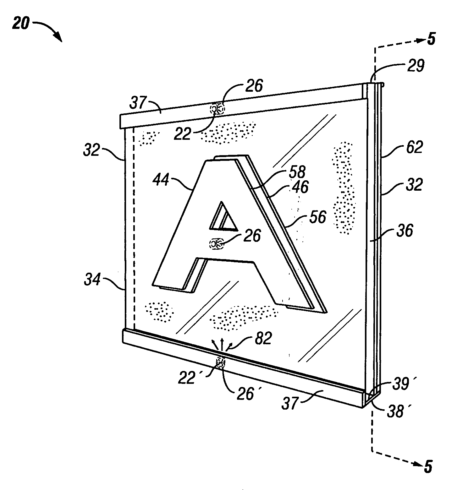
[0034] Referring to FIGS. 4 and 5, there is shown a transversely-illuminated display, designated generally as 20, in accordance with a first embodiment of the present invention. In the illustrated embodiment, the transparent curvilinear plastic or glass sheet 32 is flat and rectangular in shape, having two upright side edges 34, 36 and a lowermost edge 38, in addition to upper edge 29. Although a rectangular transparent sheet 32 is depicted, the transparent sheet 32 can be any shape, including round, oval, polycurved or polygonal. Transparent sheet 32 can be made from generally rigid material (such as glass) or generally flexible material, such as polycarbonate.

[0035] The display 20 comprises one or more light sources 22, that can be but need not be in the form of an LED, mounted in a recess 26 formed at or near the upper edge 29 of the transparent sheet 32, behind an opaque border 37. The display 20 can also include another light source 22, which can be an LED, mounted in a recess...


PUM


Abstract

A transversely-illuminated display including a transparent sheet with a front face and a rear face wherein the light-transparent sheet includes a light source disposed in a recess in the sheet. The display further includes a front image layer disposed on a front face of the transparent sheet and a rear image layer is disposed on a rear face of the transparent sheet substantially in registry with the front image layer, wherein the front image layer and the rear image layer are positioned so that the light within the transparent sheet will shine onto the rear image layer thereby to enhance illumination of the rear image layer. The display has a structure such that a portion of the light within the transparent sheet forms an image of a halo or aura of light surrounding the rear image layer.

Description

FIELD OF THE INVENTION [0001] The present invention relates to illuminated signs and displays. DESCRIPTION OF THE RELATED ART [0002] Edge-illuminated signs are known. In one example of an edge-illuminated sign, a transparent plastic sheet is illuminated by a light source disposed along an edge thereof so that light passes through the sheet material in a direction along the plane of the sheet. An image to be displayed is formed on one of the faces of the sheet whereby the light contrast between the image and the remainder of the sheet increases the visual impact of the image to a person viewing the sign. A typical known edge-illuminated prior art sign as illustrated in FIG. 1. [0003] Referring to FIG. 1, a transparent plastic sheet 2, typically of acrylic plastic material, which is rectangular in shape has one upper edge 4 thereof received in a lamp housing 6 in which an elongate bulb 7, typically a fluorescent bulb, and electrical fittings 9 therefor are received, the bulb extending...

Claims


Application Information

Patent Timeline
Patent Type & Authority Applications(United States)
IPC IPC(8): G09F13/18
CPCG02B6/0021G02B6/005G09F13/02G09F13/14
Inventor HJALTASON, THOR DANIEL
Owner HJALTASON THOR DANIEL
Why Eureka
Try Eureka