Respiratory monitoring with differential pressure transducer

a technology of differential pressure transducer and respiratory monitoring, which is applied in the direction of respiratory organ evaluation, diagnostic recording/measuring, operating means/releasing devices of valves, etc., can solve the problems of adversely affecting the interpretation and/or real airflow needs of subjects

Active Publication Date: 2007-06-07
GENERAL ELECTRIC CO
View PDF73 Cites 16 Cited by
  • Summary
  • Abstract
  • Description
  • Claims
  • Application Information

AI Technical Summary

Problems solved by technology

For example, interface leaks and / or interface compressions commonly adversely effect a subject's interpreted and / or real airflow needs.
More specifically, since interface disturbances will always be difficult and / or impossible to avoid, a need exists to deal with them appropriately.

Method used


Image

  • Respiratory monitoring with differential pressure transducer
  • Respiratory monitoring with differential pressure transducer
  • Respiratory monitoring with differential pressure transducer

Examples


Embodiment Construction

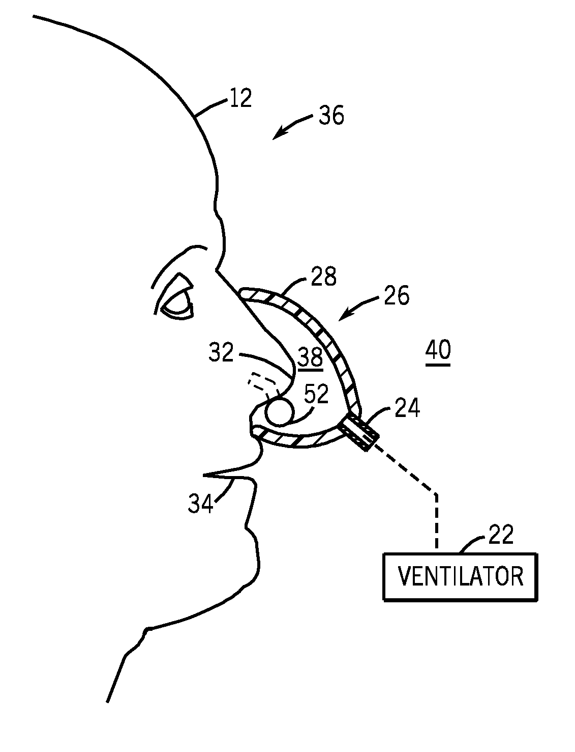
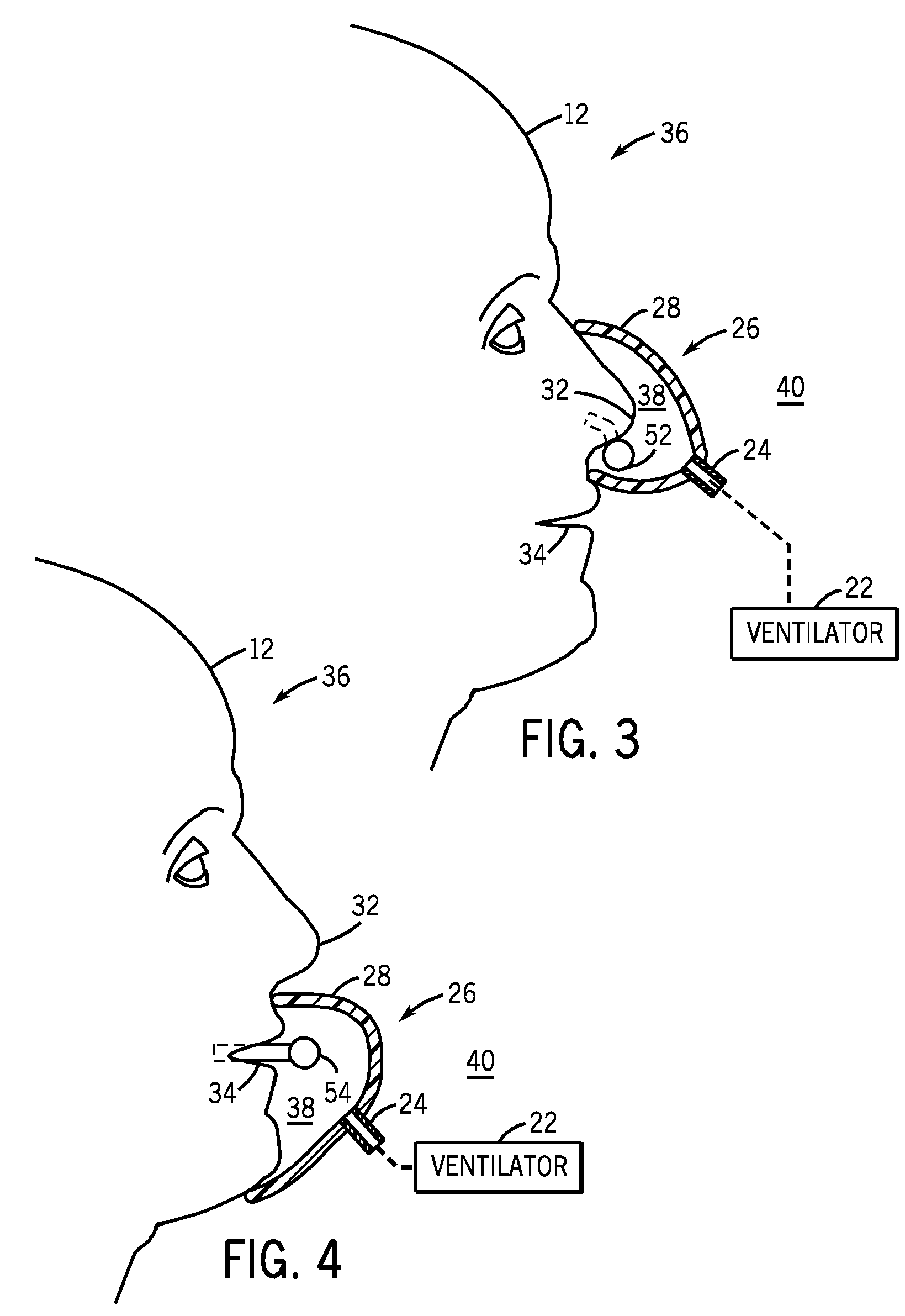
[0086] Referring now to the figures, preferred embodiments of the inventive arrangements will be described in terms of medical subjects needing respiratory care. However, the inventive arrangements are not limited in this regard. For example, while variously described embodiments provide improvements in respiratory care, and more specifically, improvements in respiratory monitoring, such as cannular improvements, particularly suited for use during non-invasive spontaneous and / or assisted mechanical ventilation, other contexts are also hereby contemplated, including various other healthcare, consumer, industrial, radiological, and inspection systems, and the like.

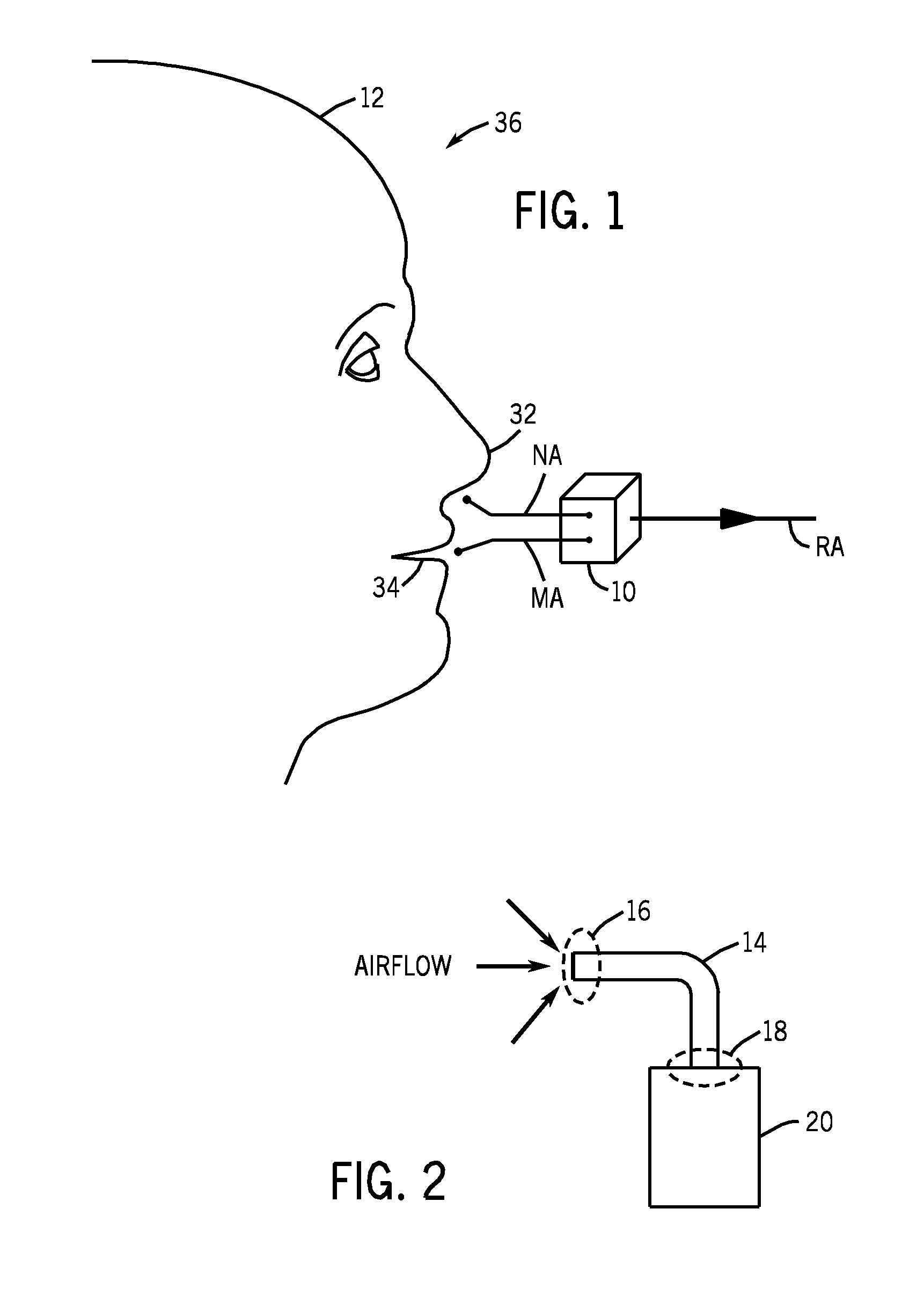
[0087] Referring now to FIG. 1, a sensor 10 is configured to receive at least partial and / or full sampling of a subject's 12 nasal airflows (“NA”) and mouth airflows (“MA”) as respiratory airflows (“RA”). Preferably, the sensor 10 is in communication with downstream electrical and / or pneumatic circuitry (not shown in FIG. 1...


PUM


Abstract

A differential pressure transducer determines pressure differentials between respiratory airflows and ambient airflows. Another determines pressure differentials between respiratory airflows and ambient airflows. And another determines pressure differentials between i) respiratory airflows received from a subject and ii) interface airflows received from an area near a cannula. Corresponding respiratory monitoring methods also determine the same.

Description

CROSS-REFERENCE(S) TO RELATED APPLICATION(S) [0001] This application is a continuation-in-part of U.S. patent application Ser. No. 11 / 315,751, which was filed on Dec. 22, 2005 and entitled “Integrated Ventilator Nasal Trigger and Gas Monitoring System” and Ser. No. 11 / 285,121, which was filed on Nov. 22, 2005 and entitled “Arrangement and Method for Detecting Spontaneous Respiratory Effort of a Patient.”STATEMENT REGARDING FEDERALLY SPONSORED RESEARCH OR DEVELOPMENT [0002] - REFERENCE(S) TO MICROFICHE APPENDIX AND / OR COPYRIGHT PROTECTION [0003] - BACKGROUND [0004] 1. Field [0005] In general, the inventive arrangements relate to respiratory care, and more specifically, to improvements in respiratory monitoring. [0006] 2. Description of Related Art [0007] For illustrative, exemplary, representative, and non-limiting purposes, preferred embodiments of the inventive arrangements will be described in terms of medical subjects needing respiratory care. However, the inventive arrangements ...

Claims


Application Information

Patent Timeline
Patent Type & Authority Applications(United States)
IPC IPC(8): A61M16/00A62B7/00F16K31/02A61B5/08
CPCA61M16/00A61M16/06A61M2016/0036A61M2230/40A61M16/021A61M16/0627A61M16/0672A61B5/08A61B5/0816A61B5/0826A61B5/087A61B5/091
Inventor ACKER, JARON MATTHEWTHAM, ROBERT QUIN YEWBILEK, KRISTOPHER JOHNTZANETAKIS, ANDREAS
Owner GENERAL ELECTRIC CO
Why Eureka
Try Eureka