
Solar energy system for hybrid vehicles

a hybrid vehicle and solar energy technology, applied in hybrid vehicles, light radiation electric generators, electrochemical generators, etc., can solve the problems of increasing vehicle cost and weight, negatively affecting efficiency, and how far the vehicle can drive, and achieve the effect of efficient development of sufficient low energy direct current (dc) electrical energy

Inactive Publication Date: 2007-06-07
SOLAR ELECTRICAL VEHICLE
View PDF9 Cites 74 Cited by
  • Summary
  • Abstract
  • Description
  • Claims
  • Application Information

AI Technical Summary

Benefits of technology

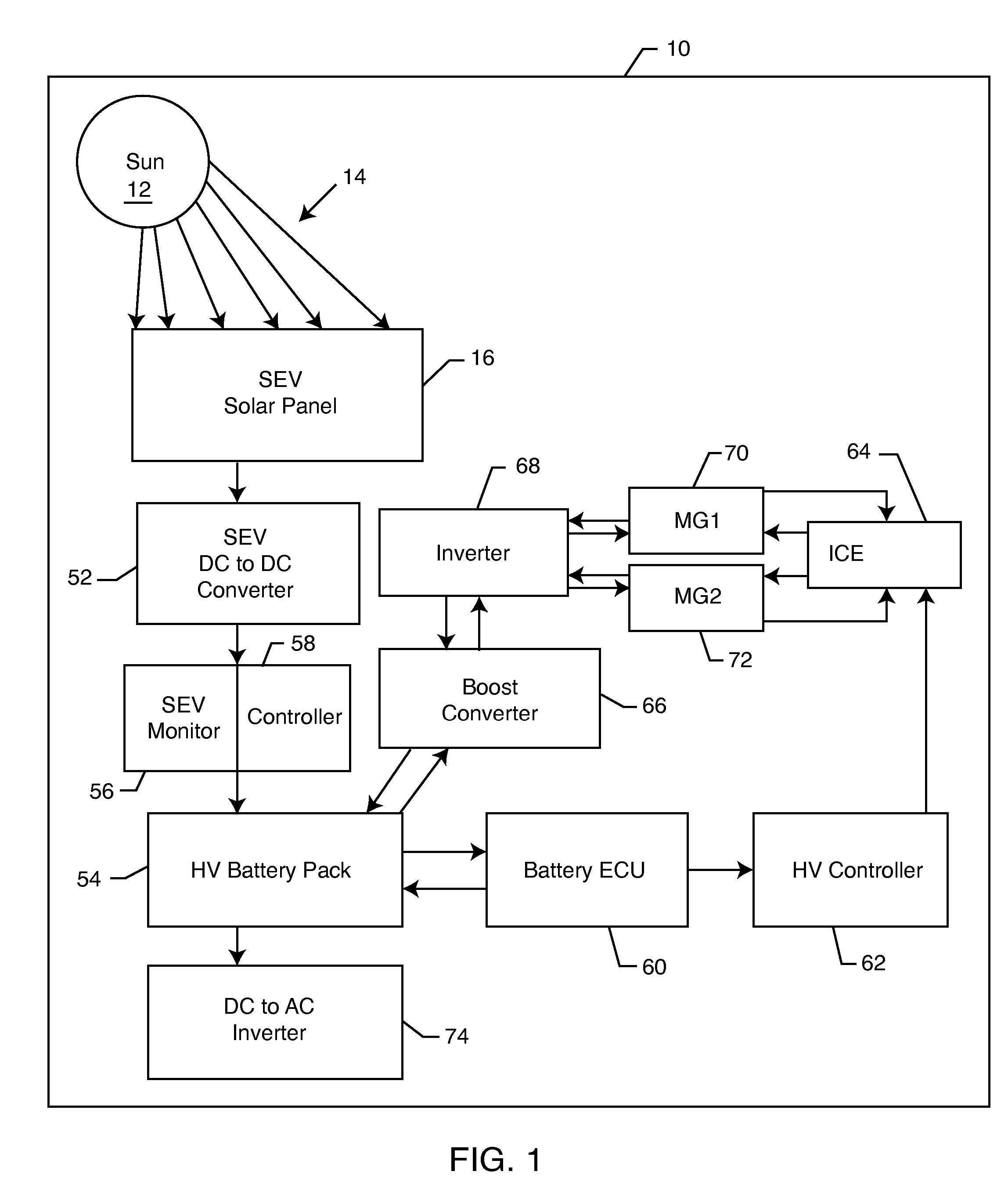
[0008] Herein disclosed is a solar energy system for a hybrid vehicle. The present invention is a clean, fully integrated solar charging system to supplement and charge a hybrid vehicle electrical system. Included in the solar energy system is a custom design low profile solar panel designed to be affixed to and fit along the contour of a hybrid vehicle roof by a panel attaching system. The solar panel efficiently develops sufficient low energy direct current (DC) electrical energy from sunlight. The low energy direct current electrical energy is transformed to high energy direct current through a DC to DC converter. The wiring harness, electrical connectors, and power converters provide a means for directing the harnessed low energy electrical energy and converted high energy electrical energy to desired locations throughout the hybrid vehicle electrical system. This high energy direct current is utilized as a supplemental energy source to charge the hybrid vehicle battery pack and supply energy to the other electrical components.
[0009] Electrical and mechanical subsystems control and monitor performance of the solar energy system of the present disclosure. The subsystems communicate with and augment the hybrid vehicle electrical system to ensure the system provides adequate renewal energy. The charge controller and system monitor ensure that the hybrid vehicle battery charge state operates at peak performance during daylight operation. The hybrid vehicle battery pack is energized both when in the hybrid vehicle is in operation an while parked. The solar energy system therefore does not require the extensive battery pack upgrade as required by the Toyota E-Drive system because the solar energy system provides continuous charge to vehicle components. The solar energy system as disclosed allows the hybrid vehicle to operate under typical driving conditions of thirty to fifty miles per day with maximum utilization of electric energy. Thus, the overall efficiency of the hybrid is increased.

Problems solved by technology

While the E-Drive System enables the hybrid vehicles to operate in full electric mode for greater distances, it also presents some drawbacks.
Larger batteries increase vehicle cost and weight thereby negatively affecting efficiency.
The system has limitations on how far the vehicle can drive in pure electric mode, thus limiting total fuel economy.

Method used


Image

  • Solar energy system for hybrid vehicles
  • Solar energy system for hybrid vehicles
  • Solar energy system for hybrid vehicles

Examples


Embodiment Construction

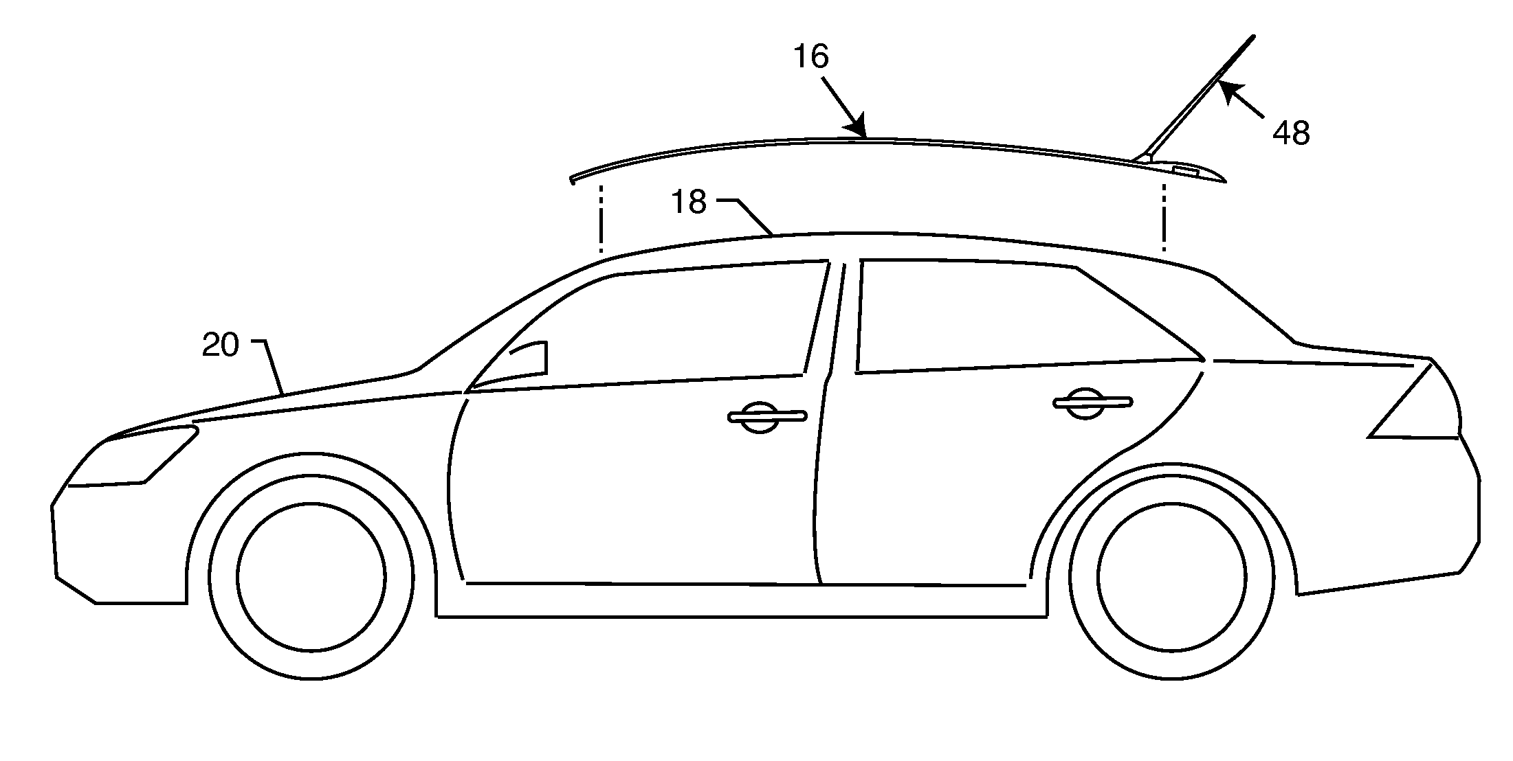
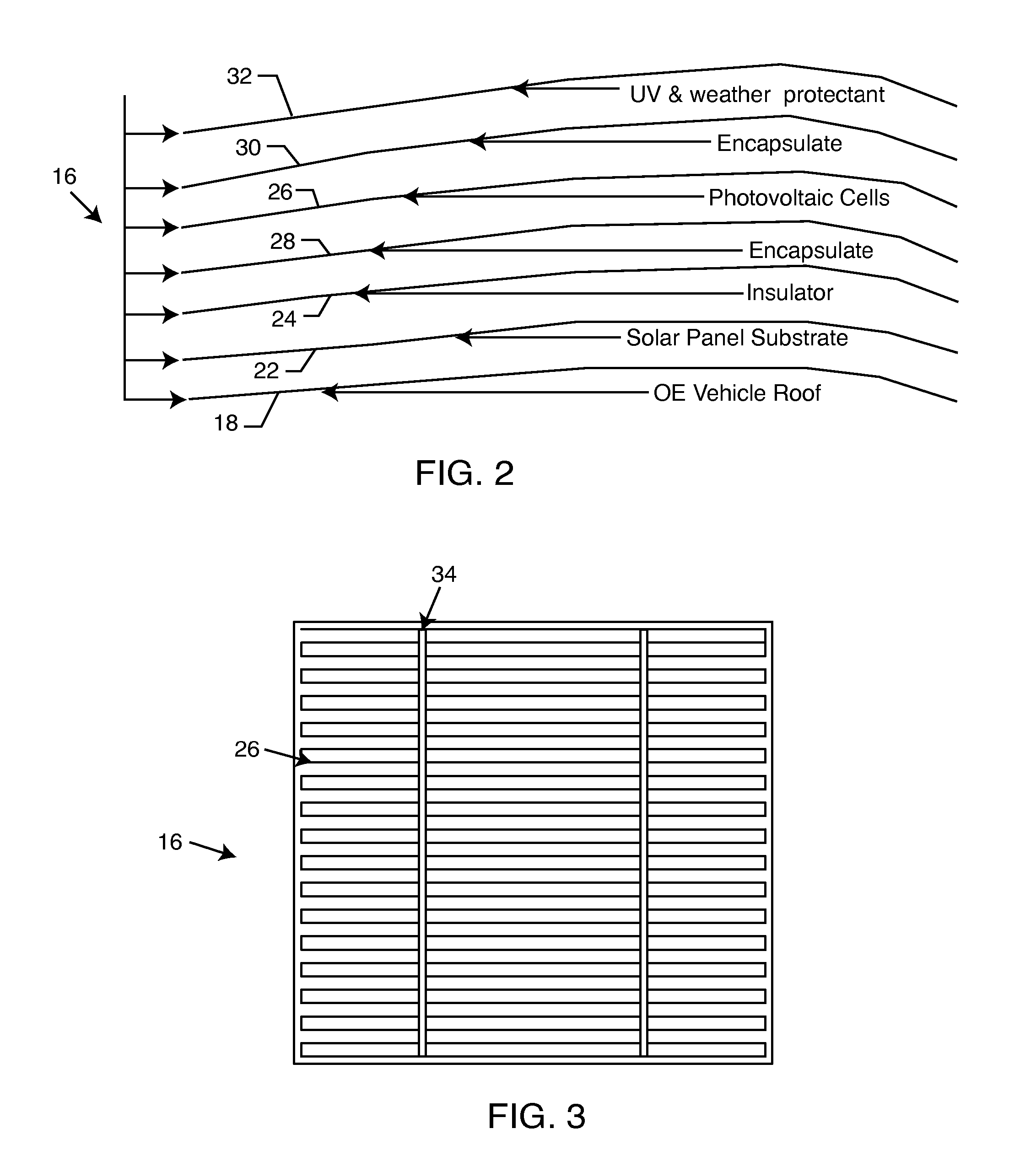
[0020] As shown in the exemplary drawings for purposes of illustration, the present disclosure for a solar energy system for a hybrid vehicle is referred to generally by the reference numeral 10. Turning now to the representative figures in the specification, FIG. 1 illustrates the basic energy flow of a solar energy system 10 as incorporated into the electrical system of a hybrid vehicle. In FIG. 1, a sun 12 irradiates sunlight 14 upon a solar panel 16. FIG. 7 shows the solar panel 16 sized and configured to overly a roof 18 of a hybrid vehicle 20 (FIG. 7). A person of ordinary skill in the art will readily recognize that the solar panel 16 could be configured to fit the roof 18 of vehicles having many different configurations. The hybrid vehicle 20 illustrated in FIG. 7 is merely a sample embodiment. The solar panel 16 could be utilized in vehicles that include, but not limited to, cars, trucks, sport utility vehicles, commercial vehicles, buses, and other vehicles having a roof o...


PUM


Abstract

A solar energy system for a hybrid vehicle that utilizes an attachable solar panel to receive and convert solar energy into direct current electricity. A wiring harness directs the direct current electricity generated by the solar panel to a converter. The converter transforms the direct current electricity from a comparatively lower energy state to a comparatively higher energy state.

Description

BACKGROUND OF THE INVENTION [0001] The present invention is generally directed a solar energy system. More particularly, the present invention relates to a solar energy system for incorporation into hybrid vehicles as a supplemental power source. [0002] A hybrid vehicle or gas-electric hybrid powered vehicle uses a mixture of technologies such as internal combustion engines (ICES), electric motors, gasoline, and batteries. Such vehicles supplement, or at times even replace, the power generated from the gasoline internal combustion engine with electric power, such as that stored in the batteries. Electricity within the batteries can come from several sources, including: generators coupled to the combustion engine or electricity derived from moving parts of the vehicle, such as the wheels. [0003] The Energy CS, Clean Tech and Valence Technology companies co-developed what is referred to as the E-Drive System, sometimes referred to as the “plug-in hybrid” system. In such a system, the ...

Claims


Application Information

Patent Timeline
IPC IPC(8): H02N6/00
CPCH01M10/465Y02E10/50B60K6/22B60K16/00B60K2016/003B60W20/00H01L31/048Y02T10/90B60L53/51Y02T10/70Y02T90/12Y02T10/7072Y02E60/10
Inventor JOHANSON, JAMES GREGORYBAGNALL, MARK
Owner SOLAR ELECTRICAL VEHICLE
Learn More