Microfluidic device for cell and particle separation

a microfluidic device and particle technology, applied in electrostatic separators, diaphragms, electrolysis, etc., can solve the problems of complex valves and pumps, poor discrimination of methods, and many of the proposed sorting schemes

Active Publication Date: 2007-06-07
RGT UNIV OF CALIFORNIA
View PDF5 Cites 94 Cited by
  • Summary
  • Abstract
  • Description
  • Claims
  • Application Information

AI Technical Summary

Benefits of technology

[0007] In one embodiment of the invention, a microfluidic separation device includes a microchannel formed in a substrate and being defined at least by a bottom surface, a first side wall, and second side wall. Fluid containing particles or cells is flowed through the microchannel from an upstream end to a downstream end. The downstream end terminates in a plurality of branch channels. A plurality of vertically-oriented electrodes are disposed on the first wall and on the second wall opposite to the first wall. A voltage source is connected to the plurality of opposing electrodes to drive the electrodes. The opposing, vertically-oriented electrodes may be used to focus a heterogeneous population of particles or cells for subsequent downstream separation via additional electrodes placed on one of the side walls. Alternatively, the opposing, vertically-oriented electrodes may be used to spatially separate a heterogeneous population of particles or cells for later collection in one or more of the branch channels.

Problems solved by technology

Unfortunately, many of the proposed sorting schemes set forth above have significant limitations.
Also, this method suffers from poor discrimination since the particles / cells located at the sides of the microchannel can be eluted along with the “faster” fraction located within the central region of the channel.
Because of this, complicated valves and pumps are needed if this type of separation approach were integrated with other sample preparation steps.

Method used


Image

  • Microfluidic device for cell and particle separation
  • Microfluidic device for cell and particle separation
  • Microfluidic device for cell and particle separation

Examples


Embodiment Construction

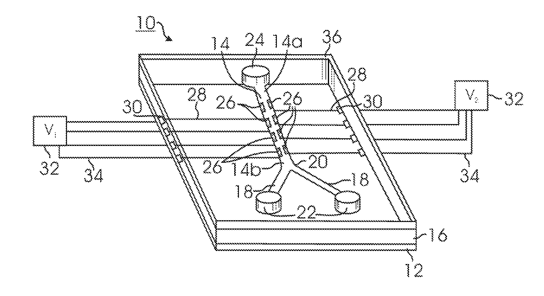
[0027]FIG. 1 illustrates a microfluidic device 10 according to one embodiment of the invention. The microfluidic device 10 includes a substrate 12 onto which the device 10 is formed. The substrate 12 may include a relatively inert material such as silicon, glass, polycarbonate, or a plastic-based material. The substrate 12 should be amenable to depositing the electrodes and electrical lines or traces used to drive the electrodes (discussed in more detail below).

[0028] A main or common microchannel 14 is formed in a polymer-based material 16 that overlays the substrate 12. The polymer-based material 16 may include a photoresist such as, for instance, SU-8. As seen in FIG. 1, the microchannel 14 has a length that includes an upstream region 14a, and a downstream region 14b. The terms upstream and downstream are indicative of the direction of flow of fluid and particles or cells within the microchannel 14 during operation. During operation, fluid flow (and hence flow of particles or c...


PUM

PropertyMeasurementUnit
voltageaaaaaaaaaa
conductivityaaaaaaaaaa
frequencyaaaaaaaaaa

Abstract

A microfluidic separation device includes a microchannel formed in a substrate and being defined at least by a bottom surface, a first side wall, and second side wall. Fluid containing particles or cells is flowed through the microchannel from an upstream end to a downstream end. The downstream end terminates in a plurality of branch channels. A plurality of vertically-oriented electrodes are disposed on the first wall and on the second wall opposite to the first wall. A voltage source is connected to the plurality of opposing electrodes to drive the electrodes. The opposing, vertically-oriented electrodes may be used to focus a heterogeneous population of particles or cells for subsequent downstream separation via additional electrodes placed on one of the side walls. Alternatively, the opposing, vertically-oriented electrodes may be used to spatially separate a heterogeneous population of particles or cells for later collection in one or more of the branch channels.

Description

REFERENCE TO RELATED APPLICATIONS [0001] This Application claims priority to U.S. Provisional Patent Application No. 60 / 743,220 filed on Feb. 2, 2006. The '220 application is incorporated by reference as if set forth fully herein. This Application is also a continuation-in-part of U.S. patent application Ser. No. 11 / 557,060 filed on Nov. 6, 2006, which itself claims priority to U.S. Provisional Patent Application No. 60 / 734,544 filed on Nov. 7, 2005. The '060 and '544 applications are incorporated by reference as if set forth fully herein.FIELD OF THE INVENTION [0002] The field of the invention generally relates to devices used to separate and sort particles or cells. More particularly, the invention relates to microfluidic-based devices that separate and / or sort biological materials (e.g., cells or cellular components) or particles. BACKGROUND OF THE INVENTION [0003] Microfluidic-based systems are becoming widely used in biological and chemical analysis applications. Traditionally,...

Claims


Application Information

Patent Timeline
Patent Type & Authority Applications(United States)
IPC IPC(8): H05H3/02H01S1/00H01S3/00
CPCB01L3/502761B01L2200/0647B01L2300/0829B01L2300/0864B01L2400/0424B03C5/005B03C5/026G01N15/1056G01N2015/1081C12M33/00C12M23/16
Inventor LEE, ABRAHAM P.WANG, LISENFLANAGAN MONUKI, LISAMONUKI, EDWIN S.MARCHENKO, SVYATOSLAV A.
Owner RGT UNIV OF CALIFORNIA
Why Eureka
Try Eureka