Method and apparatus for locating well casings from an adjacent wellbore

Active Publication Date: 2007-06-07
SCHLUMBERGER TECH CORP
View PDF30 Cites 120 Cited by
  • Summary
  • Abstract
  • Description
  • Claims
  • Application Information

AI Technical Summary

Benefits of technology

[0008] An embodiment of a method of locating a target wellbore containing a conductive member from a second wellbore and directing the trajectory of the second wellbore relative to the target wellbore is provided. The method includes the steps of providing a bottom hole assembly having an electric current driver with an insulated gap, at least one magnetometer positioned above or below the electric current

Problems solved by technology

Conducting locating surveys utilizing wireline tools, and relying on those results, has significant drawbacks.
For example, using wireline equipment increases rig time and costs.
Further, well

Method used


Image

  • Method and apparatus for locating well casings from an adjacent wellbore
  • Method and apparatus for locating well casings from an adjacent wellbore
  • Method and apparatus for locating well casings from an adjacent wellbore

Examples


Embodiment Construction

[0026] Refer now to the drawings wherein depicted elements are not necessarily shown to scale and wherein like or similar elements are designated by the same reference numeral through the several views.

[0027] As used herein, the terms “up” and “down”; “upper” and “lower”; and other like terms indicating relative positions to a given point or element are utilized to more clearly describe some elements of the embodiments of the invention. Commonly, these terms relate to a reference point as the surface from which drilling operations are initiated as being the top point and the total depth of the well being the lowest point.

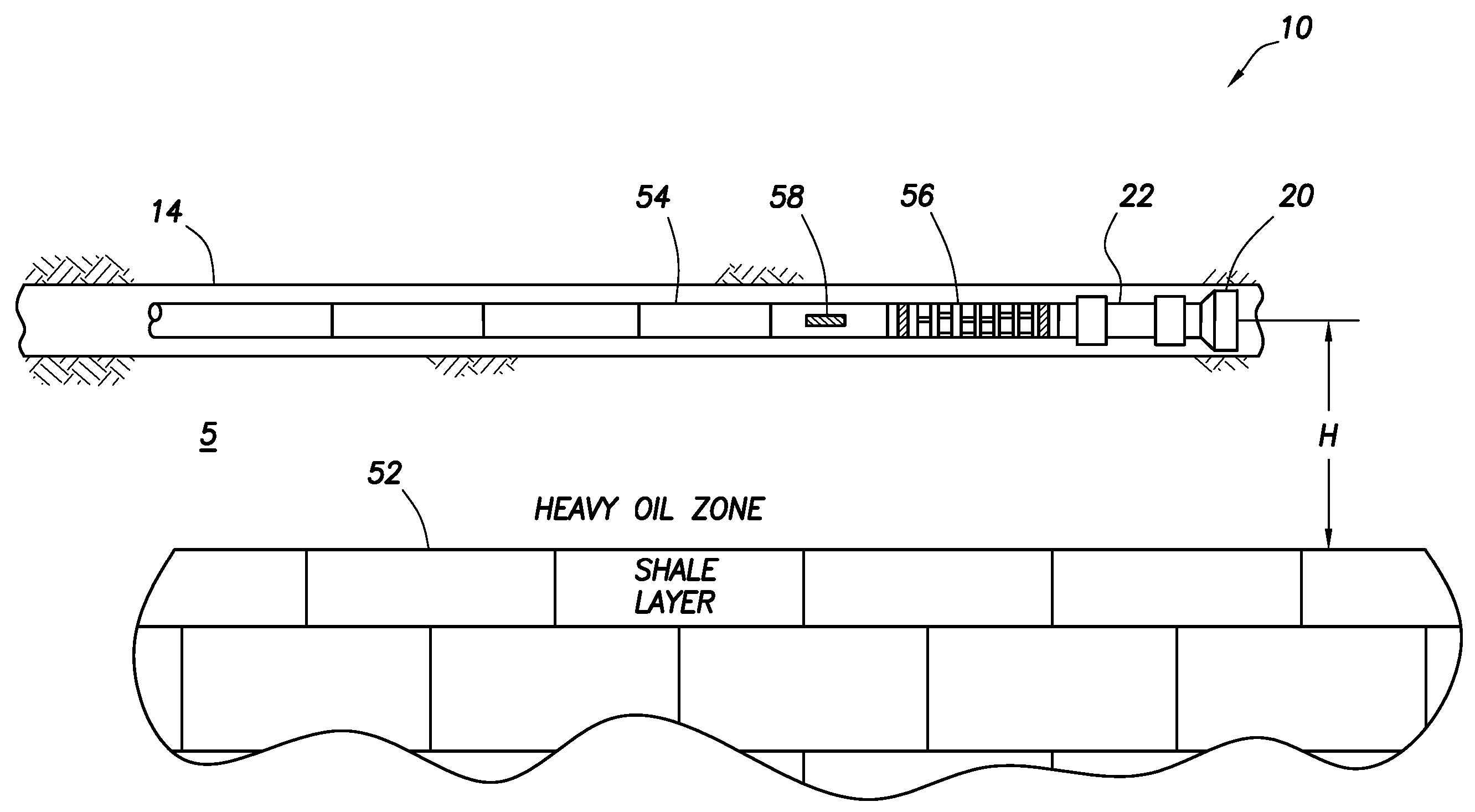
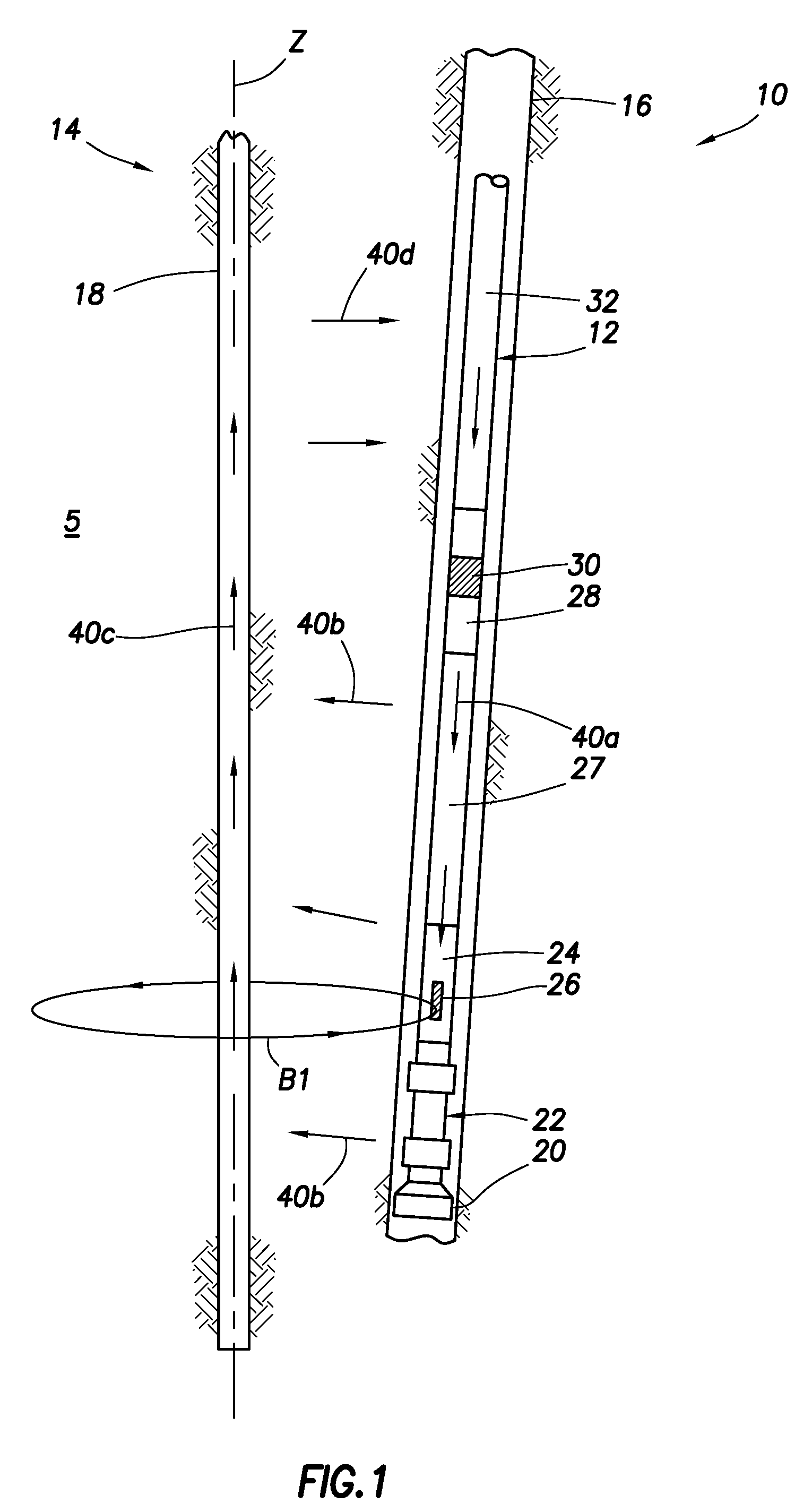
[0028]FIG. 1 is a schematic of an embodiment of a wellbore locating system 10 that includes a bottom hole assembly (“BHA”) 12 that is equipped to locate a target wellbore 14 in earthen formation 5 while the BHA 12 is used to drill a second wellbore 16 in formation 5, such that second wellbore 16 may be positioned as desired and guided along a desired trajectory. T...


PUM


Abstract

A wellbore tool for locating a target wellbore containing a conductive member from a second wellbore and directing the trajectory of the second wellbore relative to the target wellbore includes an electric current driver having an insulated gap; a three-axis magnetometer positioned within a non-magnetic housing that is disposed within a non-magnetic tubular, the three-axis magnetometer positioned below the electric current driver; a drill bit positioned below the three-axis magnetometer; a hollow tubular connected between the electric current driver and the three-axis magnetometer; and a measurement-while-drilling tool. The current driver generates an electric current across the gap to the portion of the tool below the insulated gap. In a method a current is generated across the insulated gap to the portion of the tool below the insulated gap to the conductive material in the target wellbore returning to a portion of the bottom hole assembly above the insulated gap thereby producing a target magnetic field. Measuring the target magnetic field at the bottom hole assembly and the earth's magnetic field; and determining the position of the second wellbore relative to the target wellbore. Then steering the bottom hole assembly to drill the second wellbore along a trajectory relative to the target wellbore.

Description

RELATED APPLICATIONS [0001] This application claims the benefit of U.S. Provisional Patent Application No. 60 / 733,347 filed on Nov. 4, 2005.FIELD OF THE INVENTION [0002] The present invention relates in general well drilling operations and more particularly to locating a casing or drill string of a first wellbore from a second wellbore while drilling the second wellbore. BACKGROUND [0003] In various drilling operations it is desirable to locate adjacent wellbores. Examples of drilling operations which may require locating adjacent wellbores, include relief drilling, drilling U-shaped wells, and steam assisted gravity drainage (SAGD). From time to time wells blowout and it is desired to kill the well subsurface, thus it is necessary to accurately position the first well while drilling the second intercepting relief wellbore. Currently, a common application for locating adjacent wellbores occurs when drilling a second wellbore substantially parallel to a first wellbore such as in SAGD...

Claims


Application Information

Patent Timeline
IPC IPC(8): G01V3/08
CPCE21B47/02216G01V3/26E21B47/0228
Inventor CLARK, BRIANDUPUIS, CHRISTOPHEMINERBO, GERALD N.
Owner SCHLUMBERGER TECH CORP
Why Eureka
Try Eureka