
Apparatus and method for hydraulic fracture imaging by joint inversion of deformation and seismicity

a technology of hydraulic fracture and joint inversion deformation, applied in the field of hydraulic fracture imaging, can solve the problems of not providing a mechanically consistent or integrated approach in the prior ar

Inactive Publication Date: 2007-06-07
THE BOARD OF TRUSTEES OF THE LELAND STANFORD JUNIOR UNIV
View PDF7 Cites 18 Cited by
  • Summary
  • Abstract
  • Description
  • Claims
  • Application Information

AI Technical Summary

Benefits of technology

[0006] In view of the shortcomings of the prior art, the present invention provides a method for hydraulic fracture imaging that takes full advantage of deformation data and seismic or micros...

Problems solved by technology

Unfortunately, the prior art does not provide a mechanically consistent or integrated approach for using deformation data in conjunction with the seismicity to achieve effective and efficient fracture imaging.

Method used


Image

  • Apparatus and method for hydraulic fracture imaging by joint inversion of deformation and seismicity
  • Apparatus and method for hydraulic fracture imaging by joint inversion of deformation and seismicity
  • Apparatus and method for hydraulic fracture imaging by joint inversion of deformation and seismicity

Examples


Embodiment Construction

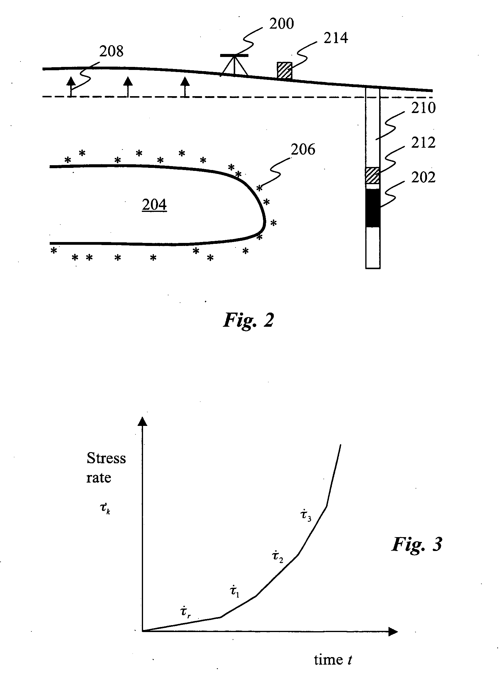
[0020] The present invention provides a method of fracture imaging that combines deformation and seismic mapping in a mechanically consistent and integrated fashion. This innovative combination begins with the recognition that the earthquakes respond to changes in stress caused by the propagation of the hydraulic fracture. The forward problem (i.e., to predict the earthquakes knowing the fracture evolution) is as follows: 1) Compute the stress change due to the fracture at all points near the fracture as a function of space and time using methods of elastic crack theory; 2) use Dieterich's seismicity rate theory to predict the rate of earthquake activity as a function of space and time. The integrated rate gives the cumulative number of earthquakes recorded in each voxel around the fracture. One may then invert this problem, i.e., take the measured tilts and earthquake locations and determine the position of the fracture at any given instant in time.

[0021] A principal advantage of ...


PUM


Abstract

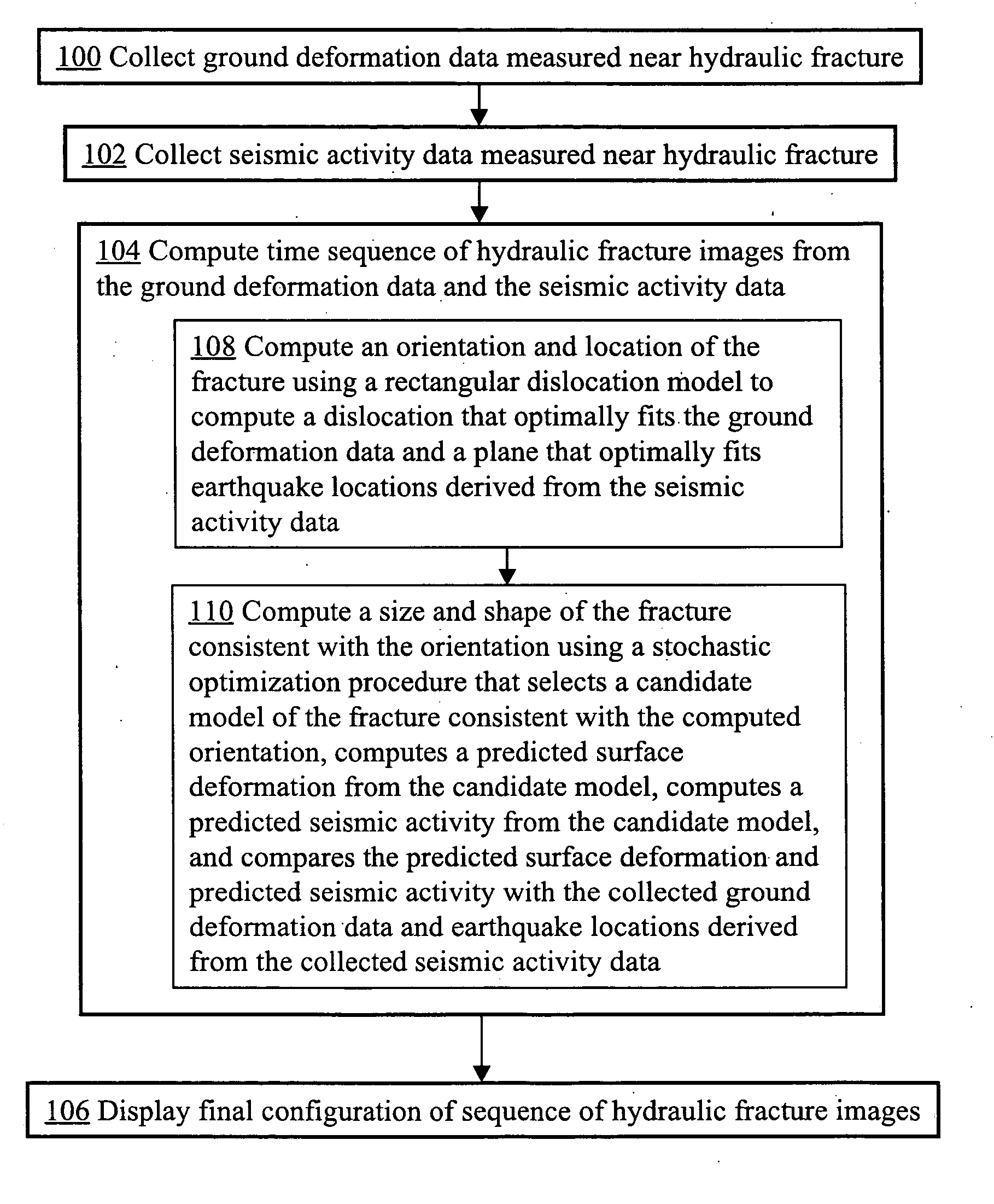
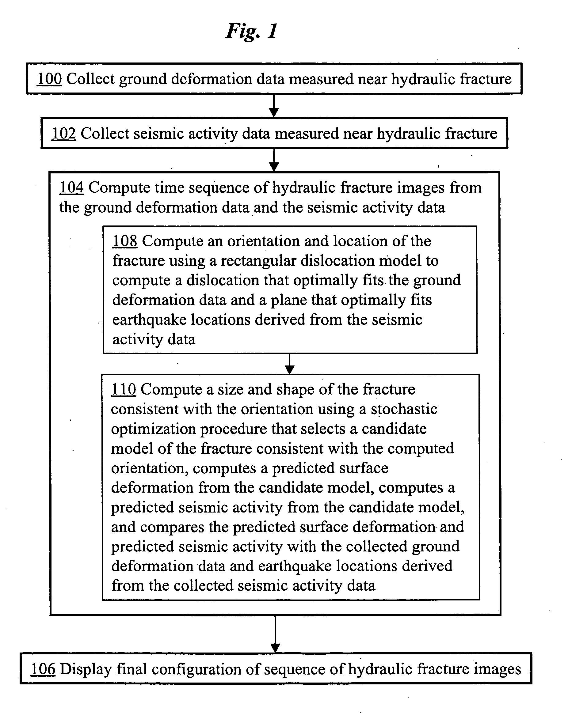
A method for hydraulic fracture imaging consistently integrates ground deformation data and microseismic data. A time sequence of hydraulic fracture images is computed from the combined data by first computing an orientation and location of the fracture. A size of the fracture (e.g., length, width, and opening) and detailed shape is then computed consistent with the computed orientation using a stochastic optimization procedure. This procedure may be performed by selecting a candidate model of the fracture consistent with the computed orientation, computing a predicted surface deformation from the candidate model (e.g., using elastic crack theory), computing a predicted seismic activity from the candidate model (e.g., using Dieterich seismicity rate theory), and comparing the predicted surface deformation and predicted seismic activity with the collected ground deformation data and earthquake locations derived from the collected seismic activity data.

Description

CROSS-REFERENCE TO RELATED APPLICATIONS [0001] This application claims priority from U.S. provisional patent application No. 60 / 742,718 filed Dec. 5, 2005, which is incorporated herein by reference.FIELD OF THE INVENTION [0002] The present invention relates generally to hydraulic fracture imaging. More specifically, it relates to techniques for imaging hydraulic fractures by combining both ground deformation and seismic mapping in a mechanically consistent manner. BACKGROUND OF THE INVENTION [0003] The petroleum industry uses hydraulic fracturing to increase rock permeability thereby increasing the flow of oil to producing wells. More than 75% of US oil wells are hydraulically fractured. Internationally, the fraction is closer to 20% but some expect this to increase to 75% in the next few decades. [0004] The operators need to know as much as possible about the induced fracture, including its orientation, length, whether it extends symmetrically from the borehole, its vertical extent...

Claims


Application Information

Patent Timeline
IPC IPC(8): G01V1/00
CPCG01V1/306
Inventor SEGALL, PAULYUN, SANG-HO
Owner THE BOARD OF TRUSTEES OF THE LELAND STANFORD JUNIOR UNIV
Learn More