Voltage indicator test mechanism

a voltage indicator and test mechanism technology, applied in electrical testing, measurement devices, instruments, etc., can solve the problems of not being able not having a means to etc., to improve safety and reliably provide zero energy state indication.

Active Publication Date: 2007-06-14
GRACE TECH
View PDF16 Cites 57 Cited by
  • Summary
  • Abstract
  • Description
  • Claims
  • Application Information

AI Technical Summary

Benefits of technology

[0006] It is a further object, feature, or advantage of the present invention to provide a voltage indicator to improve safety.
[0007] It is a further object, feature, or advantage of the present invention to reliably provide a zero “OFF” energy state indication.
[0008] It is a further object, feature, or advantage of the present invention to provide a test feature so that an operator can discern between a zero state and a failure state.
[0009] One or more of these and / or other objects, features, or advantages of the present invention will become apparent from the specification and claims that follow.
[0010] The inventor has recognized the problem of needing to discern between a failure state and an off state. The present invention provides for a test feature that allows an electrician or other to see a device transition from non-energized (Dead) to energized (Live).
[0011] According to one aspect of the present invention an electrical safety monitor is provided. The electrical safety monitor includes line inputs for an L1, an L2, an L3, and a GND three-phase connections, a line monitoring circuit having a plurality of light indicators and configured to produce light if voltage exists between any two of the line inputs to thereby indicate presence of voltage to a user, and a current generating circuit electrically connected to the line monitoring circuit and adapted to generate a test current to the line inputs to transition the device from dead to live, thereby allowing the user to discern between a failure state of the line monitoring circuit and an off state of the line monitoring circuit. The current generating circuit may include a magnet and the current generating circuit may be adapted to induce the test current in response to movement of the magnet, either linear movement or rotational movement. The current generating circuit may include an electroactive material adapted for transducing mechanical movement into the test current, such as a piezoelectric element. The current generating circuit may include a stored charge circuit adapted for injecting the test current in response to activation of a switch. The current generating circuit may include a photocell adapted for generating the test current. The current generating circuit may include a spring loaded crank adapted for generating the test current.

Problems solved by technology

Despite the advances of Clarke and other prior art devices, problems remain.
In particular, there is not a means to reliably provide a zero “OFF” energy state indication.
However, once it is in the dead state it cannot provide a positive indication of zero energy.
In other words, if the user disconnects the power from the electrical system, one cannot discern between failure and an off state of the voltage indicator.

Method used


Image

  • Voltage indicator test mechanism
  • Voltage indicator test mechanism
  • Voltage indicator test mechanism

Examples


Embodiment Construction

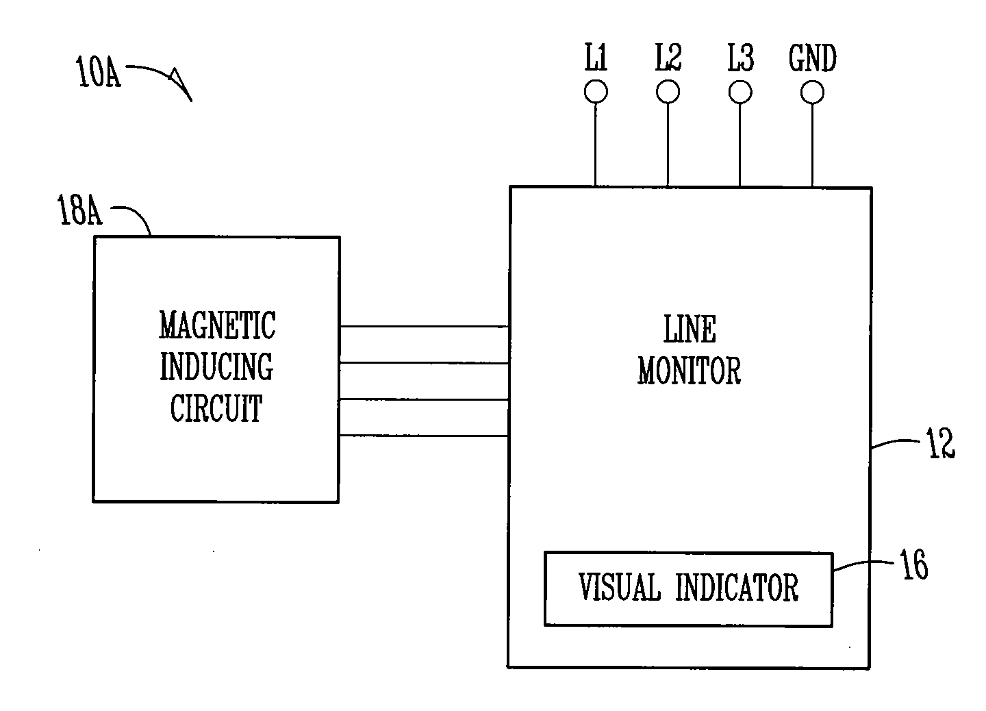
[0021] The present invention provides for injecting a test current into a circuit so that an electrician can see the device transition from dead to live. Observing this transition allows an electrician or other operator to know that the device is in the off state. Without seeing the transition, the operator would not necessarily know whether the device was truly in an off state or whether the device was in a dead state.

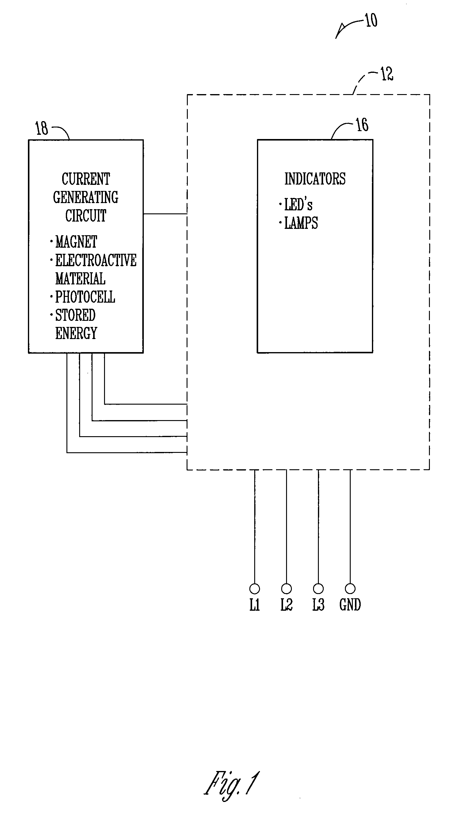
[0022]FIG. 1 provides a block diagram of one embodiment of the present invention. In FIG. 1 a device 10 is shown. The device 10 includes a line monitor device 12 having indicators 16 such as light emitting diodes (LEDs) or lamps. A current generating circuit 18is in electrical communication with the line monitoring device 12. The current generating circuit 18 may include a magnet, an electroactive material such as a piezoelectric element, a photocell, a circuit which stores energy, a spring loaded crank, or other element or configuration which is adapted for injectin...


PUM


Abstract

An electrical safety monitor includes line inputs for an L1, an L2, an L3, and a GND three-phase connections, a line monitoring circuit having a plurality of light indicators and configured to produce light if voltage exists between any two of the line inputs to thereby indicate presence of voltage to a user, and a current generating circuit electrically connected to the line monitoring circuit and adapted to generate a test current to the line inputs to transition the device from dead to live thereby allowing the user to discern between a failure state of the line monitoring circuit and an off state of the line monitoring circuit. The current inducing circuit can include a magnet which induces the test current, stored energy, a photocell, an electroactive material or other means for generating the test current.

Description

CROSS-REFERENCE TO RELATED APPLICATIONS [0001] This application claims priority under 35 U.S.C. §119 of a provisional application Ser. No. 60 / 748,460 filed Dec. 8, 2005, which application is hereby incorporated by reference in its entirety.BACKGROUND OF THE INVENTION [0002] The present invention relates to electrical safety, and more particularly to monitoring of AC voltages using voltage indicators. A voltage indicator is generally a low cost device that pre-verifies electrical isolation before maintenance personnel open a control panel and risk exposure to hazardous voltages. Typically mounted to the panel exterior and hardwired into the load side of the main disconnect, this device provides electrical maintenance with an additional safety value. Easy to apply, low cost, quick installation, and inherent reliability makes a voltage indicator a very effective electrical safety device. [0003] Creating and insuring an electrically safe work condition is critical for electricians perfo...

Claims


Application Information

Patent Timeline
Patent Type & Authority Applications(United States)
IPC IPC(8): G01R31/08
CPCG01R19/155G01R35/00
Inventor ALLEN, PHILIP BROWN JR.
Owner GRACE TECH
Why Eureka
Try Eureka