
Zero-Order Energy Smart Antenna and Repeater

a technology of applied in the field of zero-order energy smart antennas and repeaters, can solve the problems of unsuitable smart antenna designs for these systems, achieve the effects of reducing transmission power, facilitating greater communication distances, and improving signal reception and transmission

Active Publication Date: 2007-06-14
UNIV OF SOUTH FLORIDA +1
View PDF10 Cites 33 Cited by
  • Summary
  • Abstract
  • Description
  • Claims
  • Application Information

AI Technical Summary

Benefits of technology

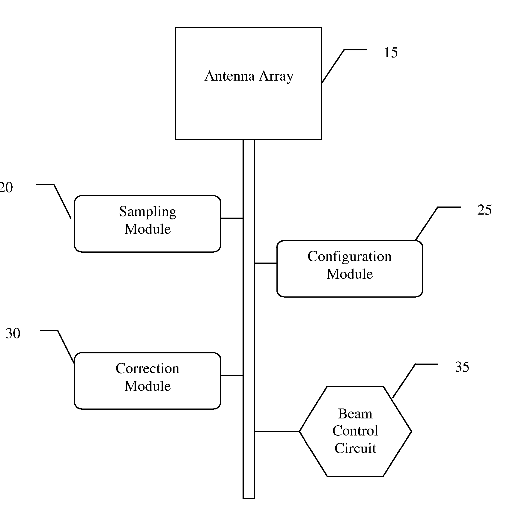
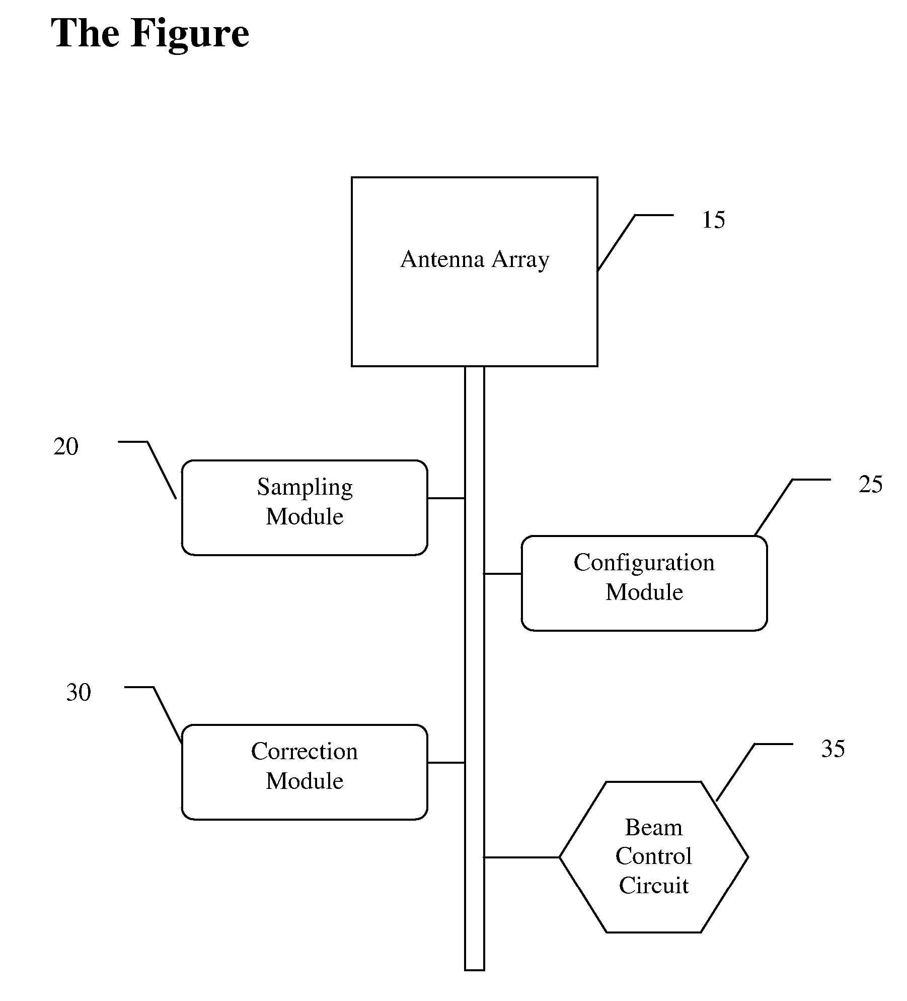
[0005] The invention has advantages in that its radiation properties can be adjusted to improve signal reception and transmission thereby enabling greater communication distances and/or lower transmission power. The key innovation of this invention is the means by which the antenna can be reconfigured. The smart ZOE antenna will consist of an N-element planar array (2-4 elements are probable) configured in an electronically-steered network that utilize...

Problems solved by technology

However, wireless sensor networks are constrained in both aspects and as such current smart antenna designs are not appropriate for these systems.

Method used


Image

  • Zero-Order Energy Smart Antenna and Repeater
  • Zero-Order Energy Smart Antenna and Repeater

Examples


Embodiment Construction

[0009] In the following detailed description of the preferred embodiments, reference is made to the accompanying drawings, which form a part hereof, and within which are shown by way of illustration specific embodiments by which the invention may be practiced. It is to be understood that other embodiments may be utilized and structural changes may be made without departing from the scope of the invention.

[0010] Adaptive Antenna

[0011] The present invention is an antenna architecture that is autonomously reconfigured on an as-needed basis depending on temporal channel characteristics, and thereby consumes only minimum DC power (Zero-Order Energy, or ZOE). The term Smart Antenna (also known as adaptive antenna) refers to a system of antenna arrays equipped with signal processing algorithms that are used to identify the direction of arrival (DOA) of the signal, and use it to calculate beamforming vectors, to track and locate the antenna beam on a target. Alternatively, the antenna is ...


PUM


Abstract

The invention is a new device that will improve the radio link quality for low power wireless devices. An example application is for low power, miniaturized wireless sensor nodes that are statically deployed in a slowly varying environment or that have limited mobility. The device is a reconfigurable antenna that is novel in that it operates with very low (zero-order) energy in contrast to existing system that required both significant computational and DC power.

Description

CROSS REFERENCE TO RELATED APPLICATIONS [0001] This application claims priority to U.S. Provisional Application No. 60 / 597,548, filed Dec. 8, 2005 and U.S. Provisional Application 60 / 825,735 filed Oct. 31, 2006, which are incorporated herein by reference.BACKGROUND OF THE INVENTION [0002] Current technologies for adaptive (i.e. smart) antennas are targeted towards systems that have moderate to large amount of computational and energy resources (e.g., cellular base stations and radar systems). However, wireless sensor networks are constrained in both aspects and as such current smart antenna designs are not appropriate for these systems. Current wireless sensors currently employ antennas that are passive and thus have fixed performance. For example, typical sensor nodes utilize omni-directional designs to ensure signal reception regardless of orientation. [0003] SUMMARY OF INVENTION [0004] The Zero Order Energy (ZOE) antenna is a self-optimizing antenna configuration that will automa...

Claims


Application Information

Patent Timeline
IPC IPC(8): H01Q21/08
CPCH01Q21/08
Inventor WELLER, THOMASFROLICK, JEFF
Owner UNIV OF SOUTH FLORIDA
Learn More