Driving system for matrix type backlight module

a backlight module and driving system technology, applied in the direction of instruments, static indicating devices, etc., can solve the problems of a large loss of entire light energy utilization rate, and a far inferior development of dynamic image and color of the crt television, so as to increase the quality of dynamic image

Active Publication Date: 2007-06-14
SHENZHEN CHINA STAR OPTOELECTRONICS TECH CO LTD
View PDF4 Cites 15 Cited by
  • Summary
  • Abstract
  • Description
  • Claims
  • Application Information

AI Technical Summary

Benefits of technology

This patent describes a new way to manage the brightness and movement of multiple lights in a display screen. It uses a specialized circuit that controls when each individual light turns on or off based on instructions from a computer program. By adjusting these timestamps, the technology allows for faster switching between different screens and smoother transitions during video playback. Additionally, it enables unique forms of visual feedback like blinking or flashing patterns, improving the overall quality of the displayed images. Overall, this innovation helps create better user experiences by enhancing the performance of advanced displays.

Problems solved by technology

The technical problem addressed in this patent is how to improve the color and brightness of liquid crystal displays, particularly in the television market, by overcoming the development disadvantage of the current technology and designing a matrix type backlight module that can be adjusted rapidly and independently.

Method used


Image

  • Driving system for matrix type backlight module
  • Driving system for matrix type backlight module
  • Driving system for matrix type backlight module

Examples


Embodiment Construction

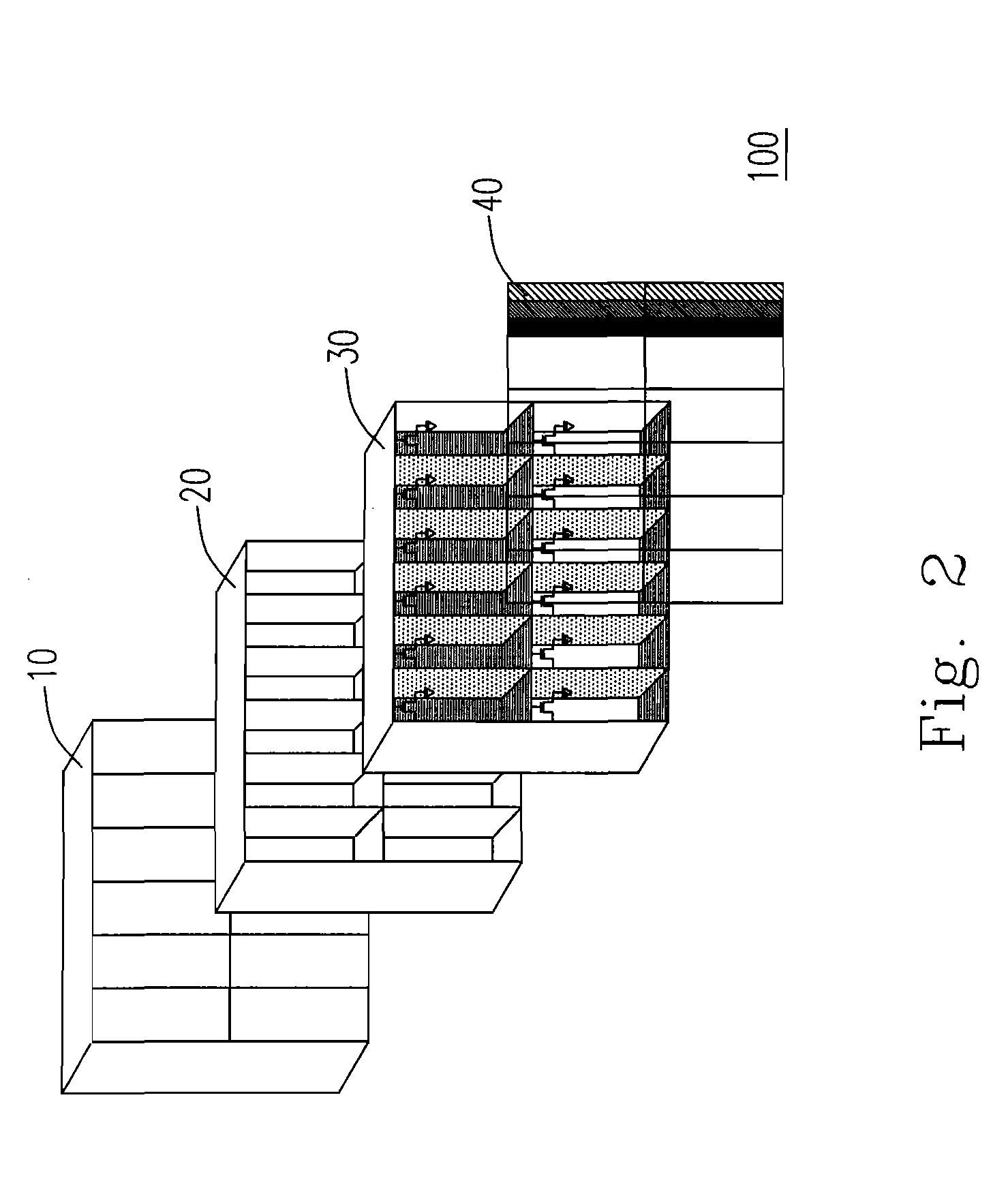
[0017] Please refer to FIG. 2, which is a schematic diagram showing the liquid crystal display device cooperating with the matrix type backlight module of the present invention. As shown in FIG. 2, the liquid crystal display device 100 comprises a matrix type backlight module 10 for forming a planar light source in which each of the plurality of light spots can be independently modulated. A black matrix layer 20 is disposed on top of the matrix type backlight module 10 to separate the light between the light spots in proximity. A thin film transistor (TFT) layer 30 is disposed on top of the black matrix layer 20 for forming each of the plurality of pixels for the liquid crystal display device. The number of pixels of the thin film transistor layer 30 can be the number of the light spots of the matrix type backlight module or its multiple, in order to make each of the plurality of light spots of the matrix type backlight module 10 corresponding to one or n of the pixels of the thin f...


PUM


Abstract

A driving system for a matrix type backlight module having a plurality of light spots is provided. The driving system includes a timing controller providing a timing signal to control a starting up sequence and a turning on time for each of the plurality of light spots, a row driver electrically connected to the timing controller and providing a turning on time of the matrix type backlight module in a row direction according to the timing signal, and a column driver electrically connected to the timing controller and providing a turning on time of the matrix type backlight module in a column direction according to the timing signal.

Description


Claims


Application Information

Patent Timeline
Owner SHENZHEN CHINA STAR OPTOELECTRONICS TECH CO LTD
Why Eureka
Try Eureka