Method for calculating an individual progressive lens

Active Publication Date: 2007-06-14
RODENSTOCK GMBH
View PDF20 Cites 29 Cited by
  • Summary
  • Abstract
  • Description
  • Claims
  • Application Information

AI Technical Summary

Benefits of technology

[0010] An object of this invention is to provide a method with which individual progressive lenses can be calculated and optimized in a very short period of time, whereby optimum properties

Problems solved by technology

However, this makes it more difficult to comply with the various requirements of hyperopias, myopias

Method used


Image

  • Method for calculating an individual progressive lens
  • Method for calculating an individual progressive lens
  • Method for calculating an individual progressive lens

Examples


Example

DETAILED DESCRIPTION OF THE DRAWINGS

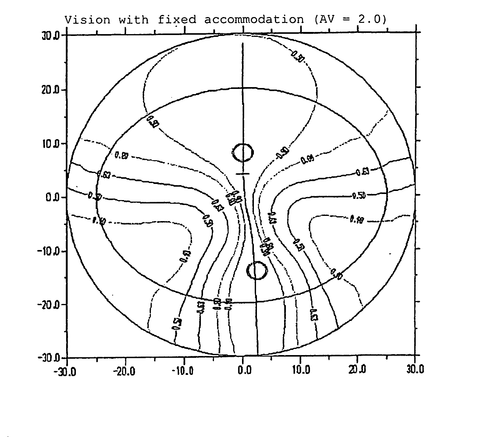
[0075] The following standard values were used in FIG. 1:

[0076] Prescribed sphere=−4.0 dpt; addition 2.0 dpt; prescribed cylinder=0 dpt; prism vertically and horizontally=0 cm / m;

[0077] Effect in the reference points in the use position; interpupillary distance=63 mm; corneal vertex distance=15 mm; ocular pivot point distance=28.5 mm; anterior tilt=8 degrees; frame lens angle (lateral tilt)=0 degrees; center thickness=2 mm; diameter=70 mm; thickness reduction prism=1.0 cm / m; material=Perfalit 1.6 n=1.597; far object distance=0 dpt; near object distance=−1000 / 380 mm; basic curve sph=3.41 dpt. FIG. 1 shows that the isolines are completely symmetrical with the principal line, and also that there is a uniform and soft transition at all points and there are large far and near vision areas. A lens having different individual parameters should also look like this.

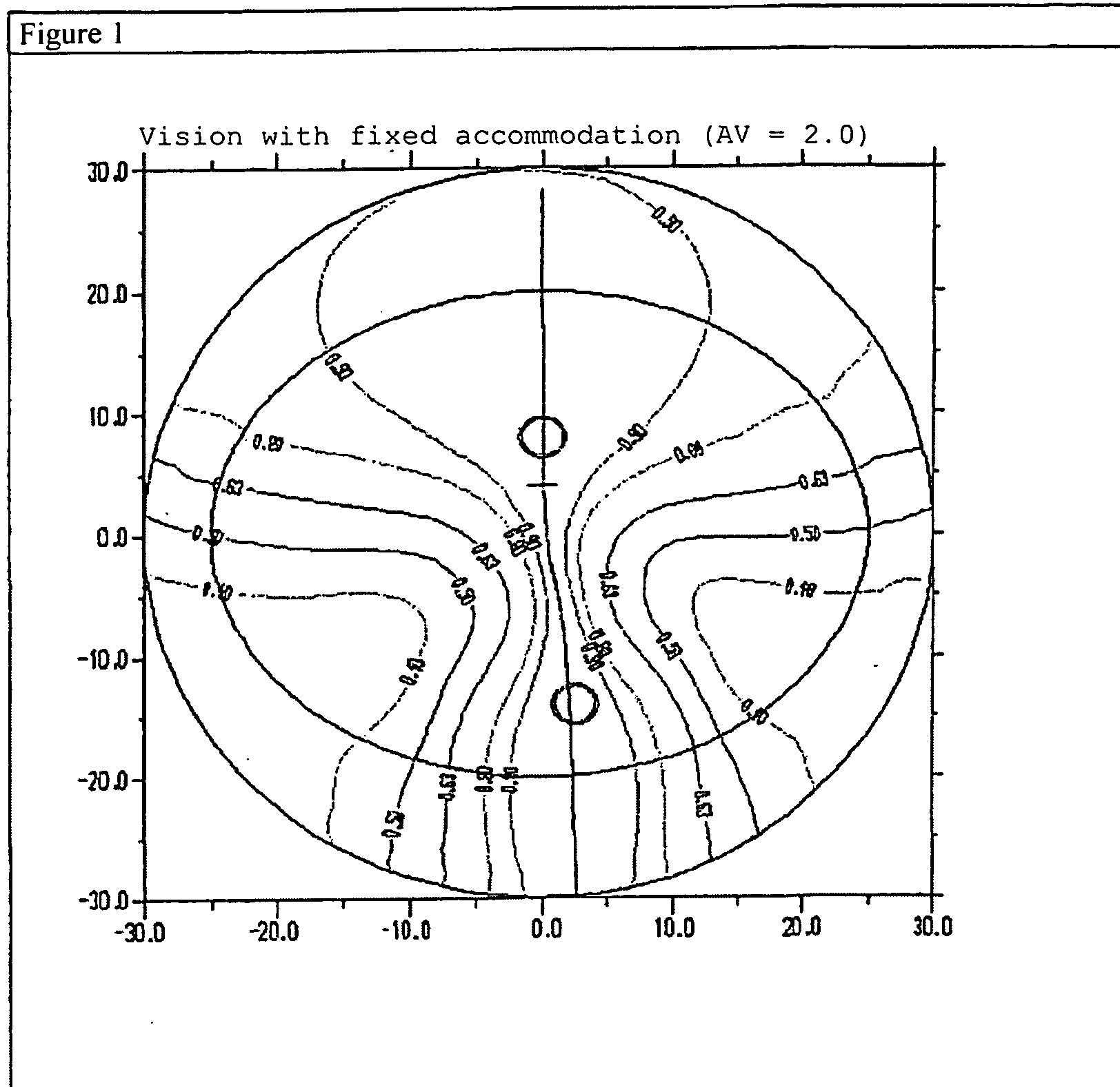
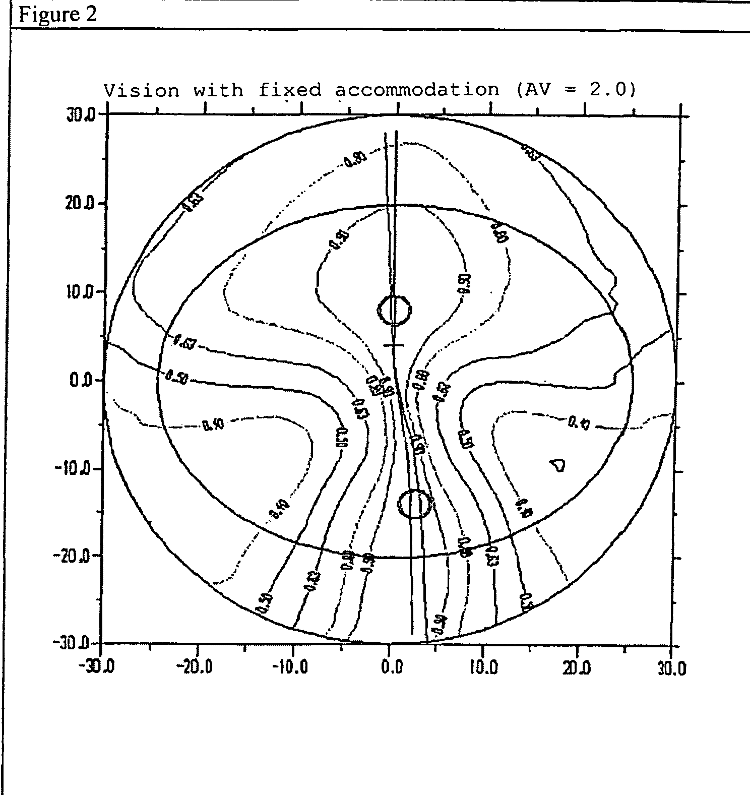
[0078] The following individual parameters are specified in FIG. 2:

[0079] Prescribed sph...


PUM


Abstract

A method of calculating an individual progressive lens creates one or more basic designs for lenses based on theoretical specifications, and then creates starting designs from these basic designs. Individual progressive lenses are calculated from the starting designs corresponding to the individual data from wearing test subjects. Valid starting designs are then created fr production. The individual lenses are calculated from the starting designs according to individual customer data.

Description

BACKGROUND OF THE INVENTION [0001] The invention relates to a method for calculating an individual progressive lens. [0002] Progressive lenses (also referred to as no-line bifocals, multifocal lenses, etc.) are usually understood to refer to lenses which have a different (lower) refractive power in the area through which the lens wearer observes an object at a greater distance-hereinafter referred to as the far part-than in the area (near part) through which the user observes a near object. The so-called progression zone is between the far part and the near part is where the effect of the lens increases continuously from that of the far part to that of the near part. The value of the increase in effect is also referred to as addition. [0003] As a rule, the far part is located in the upper part of the lens and is designed for looking “into an infinite distance” while the near part is located in the lower area of the lens and is designed for reading in particular. For special applicat...

Claims


Application Information

Patent Timeline
IPC IPC(8): G02C7/02
CPCG02C7/024G02C7/028G02C7/061
Inventor HASER, STEPHANWELK, ANDREAESSER, GREGORALTHEIMER, HELMUTHAIMERL, WALTER
Owner RODENSTOCK GMBH
Why Eureka
Try Eureka