Method of analyzing microparticle composition and microparticle composition analyzing device

Active Publication Date: 2013-01-10
THE UNIV OF TOKYO +1
View PDF0 Cites 16 Cited by
  • Summary
  • Abstract
  • Description
  • Claims
  • Application Information

AI Technical Summary

Benefits of technology

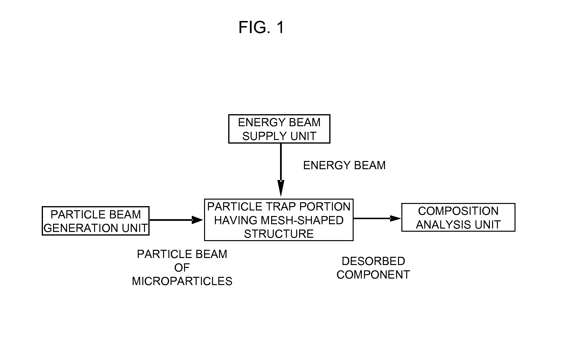
[0013]According to the method of analyzing a microparticle composition of the present invention, a particle beam of microparticles in a gas sample is converged, having removed therefrom an excess gas phase component, and further a particle trap having a mesh-shaped structure is irradiated with the particle beam of microparticles in the gas sample to capture the microparticles. Therefore, atmospheric microparticles can be efficiently condensed and captured in a relatively narrow space region. Then, the particle trap is irradiated with an energy beam to vaporize, sublimate, or react the microparticles captured by the particle trap, thereby yielding a desorbed component. Therefore, energy can be concentrated to the captured atmospheric microparticles, and a desorbed component of a high concentration can be yielded in a short period of time and analyzed. This allows the online quantitative analysis of a mass concentration of each chemical composition of atmospheric microparticles. Meanwhile, when the particle trap is irradiated with an energy beam, the atmospheric microparticles captured by the particle trap are desorbed in a short period of time, and the particle trap becomes ready to capture the subsequent microparticles. Therefore, online measurement can be performed with a high time resolution (several minutes to one hour) even with respect to an average atmospheric environment concentration level.
[0032]According to the apparatus for analyzing a microparticle composition of the present invention,

Problems solved by technology

For example, diesel microparticles are deposited in the back of the airway such as the alveoli to harm health.
As the particle size is smaller, there is a higher risk that the particles reach the alveoli through the mouth, nose, trachea, and bronchi that are organs of respiration of a human to harm health.
However, according to this method, it takes a co

Method used


Image

  • Method of analyzing microparticle composition and microparticle composition analyzing device
  • Method of analyzing microparticle composition and microparticle composition analyzing device
  • Method of analyzing microparticle composition and microparticle composition analyzing device

Examples


Example

Test Example 1

Measurement of Sulfate Aerosol

[0112]An apparatus for analyzing a microparticle composition having a configuration of an apparatus for analyzing a microparticle composition 50 illustrated in FIG. 9 was produced, and the mass concentration of ammonium sulfate particles in a gas was quantified. An aerosol containing monodisperse ammonium sulfate particles was generated by spraying and drying an ammonium sulfate aqueous solution to generate polydisperse particles, and then the polydisperse particles were allowed to pass through a classification device of a differential mobility analyzer (DMA).

[0113]The apparatus for analyzing a microparticle composition was adjusted so that the pressures in the chambers of the vacuum chambers 11a, 11b, and 11c were set to be 10−3 to 10−2 [Torr], 10−5 to 10−4 [Torr], and 10−7 to 10−6 [Torr], respectively, and the flow rate of a gas to be introduced into the aerodynamic lens 1 was 80 to 90 [cc / min]. After air as a carrier gas was preliminary...

Example

Test Example 2

Linearity and Quantitativity of Measurement

[0115]A test similar to Test Example 1 was conducted by changing the mass concentration of ammonium sulfate particles in an aerosol to be introduced into the apparatus from 36, 37, 52, 61, 93, 137, to 199 μg / m3. FIG. 14 shows a relationship between an accumulated mass of a microparticles introduced into the apparatus and a time integration amount of ion signals (sum of m / z 48 and m / z 64).

[0116]As a result, the accumulated mass of microparticles and the time integration amount of ion signals had a positive correlation, and satisfactory linearity was exhibited in the correlation therebetween in the range of the mass of microparticles subjected to the test. Thus, it was clarified that microparticles was able to be analyzed quantitatively.

Example

Test Example 3

Measurement of Nitrate Aerosol and Analysis of Capture Efficiency of Microparticles

[0117]The particle capture efficiency of a particle trap was analyzed. An aerosol containing potassium nitrate particles was measured in the same way as in Test Example 1.

[0118]It should be noted that, in order to measure the capture efficiency, it is necessary to grasp the state in which 100% of microparticles introduced into the apparatus and applied to the particle trap were measured. Then, potassium nitrate particles coated with oil (oleic acid) were generated and measured, and the result of the measurement was grasped. More specifically, it is known from the conventional study that, when dry solid particles such as potassium nitrate and ammonium sulfate collide with a surface at a high speed, a considerable part thereof bounces off the surface, but liquid particles such as oil or solid particles which are coated with a liquid to some degree hardly bounce off the surface. In other wo...


PUM


Abstract

A method of analyzing microparticle compositions and a microparticle composition analyzing device are capable of quantitatively analyzing the mass concentration of air microparticles online for each chemical composition. The particle ray of microparticles in an air sample is converged, and is irradiated onto a narrow domain of a capture body which includes a mesh-shaped structure for capturing the microparticles in the particle ray while removing surplus gas phase components, and the microparticles are captured. Then, the narrow region is subjected to concentrated irradiation of energy rays, and the microparticles that are captured by the capture body are vaporized, sublimated or reacted to yield a desorbed component, which is analyzed.

Description

TECHNICAL FIELD[0001]The present invention relates to a method of analyzing a microparticle composition and an apparatus for analyzing a microparticle composition, which are suitable for quantifying, for example, a mass concentration of each chemical composition of microparticles floating in air (aerosol).BACKGROUND ART[0002]In recent years, there is a growing concern about an influence of an atmospheric environment on health, and for example, a new environmental standard for an atmospheric microparticle concentration has been established. For example, diesel microparticles are deposited in the back of the airway such as the alveoli to harm health. A particle size of microparticles is an important factor for a health risk. As the particle size is smaller, there is a higher risk that the particles reach the alveoli through the mouth, nose, trachea, and bronchi that are organs of respiration of a human to harm health. Thus, a standard based on an atmospheric concentration of particles...

Claims


Application Information

Patent Timeline
IPC IPC(8): G01N30/72H01J49/26
CPCG01N1/2202G01N1/2205G01N1/2208Y10T436/24G01N1/4077G01N2001/2223G01N2015/0046
Inventor TAKEGAWA, NOBUYUKINAKAMURA, TAKAYUKISAMESHIMA, YUUKITAKEI, MASAHIKOHIRAYAMA, NORITOMO
Owner THE UNIV OF TOKYO
Why Eureka
Try Eureka