Bifocal contact lens

Active Publication Date: 2007-06-14
THE VISION CRC LTD +1
View PDF4 Cites 14 Cited by
  • Summary
  • Abstract
  • Description
  • Claims
  • Application Information

AI Technical Summary

Benefits of technology

[0018] An alternative is for at least the central part of the back surface of the lens to comprise a concave surface or combination of two such surfaces, that is, any two points on the one such surface may be connected by a straight line that does not pass through the interior of the lens between those points. Optionally the concave surfaces will cover the entire back surface of the lens, however, the peripheral edge thereof need not form part of said concave surfaces. These surfaces may be combined with a narrow blending zone (possibly not in itself concave) to achieve cont

Problems solved by technology

This type of lens requires no translation, but has the drawback that two images are viewed simultaneously.
As a result, the lens is not supported or braced by the upper margin of the lower lid.
Hence, the prism component is successful in moving a soft prism bifocal contact lens to the desired low position and controlling meridional rotation but is not successful in inducing vertical lens shifts as the eye looks back and forth between distant and near objects.
Presently available soft bifocal contact lenses do not have sufficient vertical shifting action to fulfil the alternating vision principle and thus do not provide acceptable vision for both distance and near viewing.
It is recognized that theses lenses

Method used


Image

  • Bifocal contact lens
  • Bifocal contact lens
  • Bifocal contact lens

Examples


Embodiment Construction

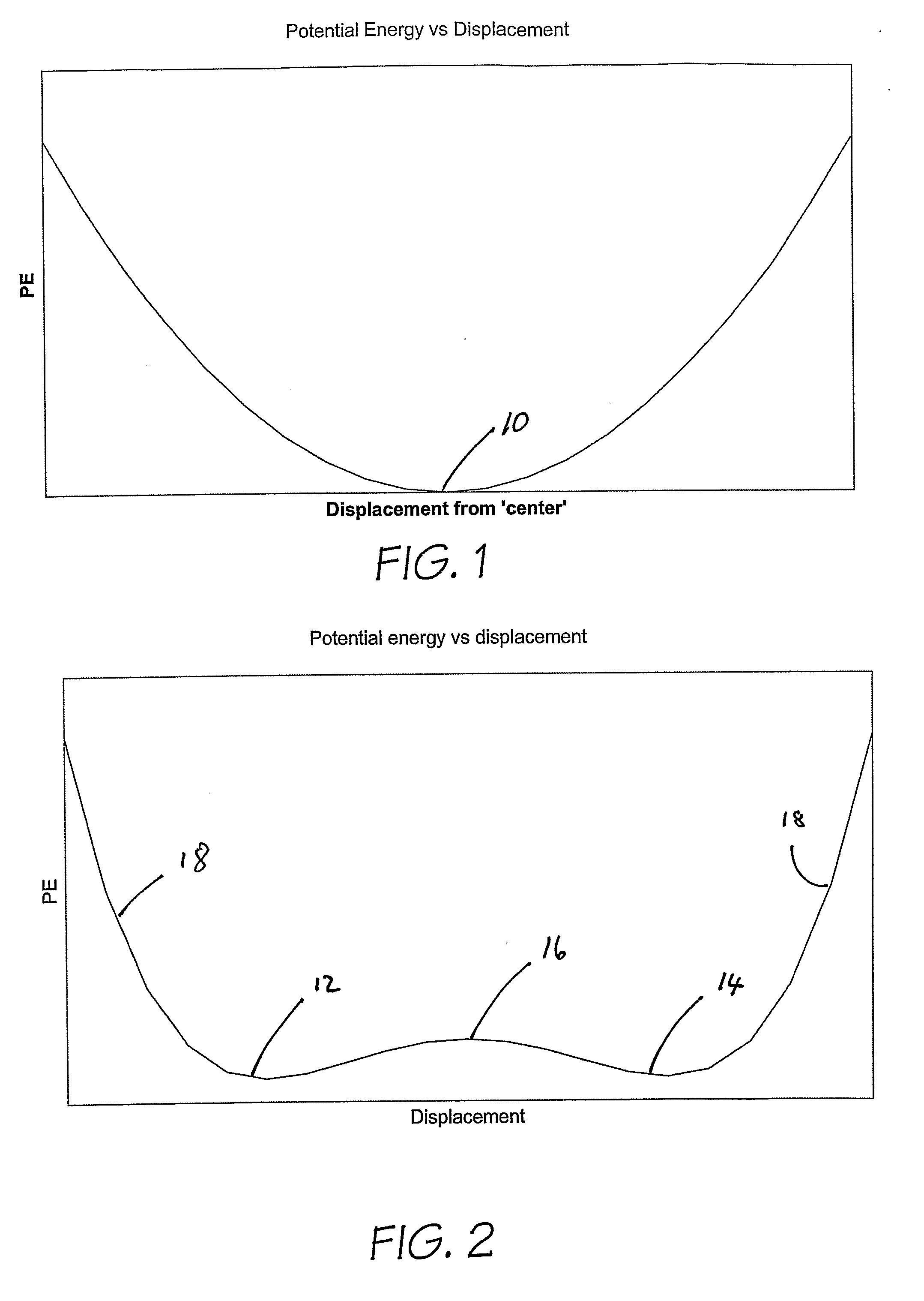
[0034] Referring initially to FIG. 1, it will be noted that the central position of the lens on the eye, indicated at numeral 10 on the graph, is the minimum potential energy position. Movement of the lens away from that position, in either direction, will increase the potential energy of the lens, and accordingly some form of external force will be required to hold the lens in the higher potential energy position.

[0035]FIG. 2, on the other hand, depicts two low potential energy points on the graph, indicated at numerals 12 and 14. These two low energy points will, in accordance with the invention, correspond with the position of the lens on the eye which corresponds with optimal positions of the contact lens for near-viewing and distance-viewing. Optionally, one of those positions is at a lower potential energy than the other position, so that the lowest potential energy position becomes more stable, making it harder to inadvertently leave this position. For safety reasons it is i...


PUM


Abstract

A contact lens having near vision and distance vision portions, the lens being movable on the eye between first and second positions, those positions corresponding with aligning the wearer's vision through the near vision and distance vision portions respectively. The lens is positionally stable on the eye in each of the two positions, and requires a force to be applied to the lens to move between the first and second positions. Preferably the lens has a back surface and a front surface, and said back surface has either one or two major back curve zones occupying a major portion of the lens back surface.

Description

FIELD OF THE INVENTION [0001] This invention relates to contact lenses, and more particularly to bifocal contact lenses in which at least one primary and one secondary optical zones are present. BACKGROUND OF THE INVENTION [0002] Bifocal lenses are comprised of two or more areas, or zones, with different optical powers, including typically a far-power zone for distance vision, and a near-power zone for near or close up vision. The two zones may be subdivided into additional power zones in which case the lens may be called a multifocal lens. [0003] The retinal image and the visual percept that results from it are dependent upon the light that enters the eye through the entrance pupil. In order for a bifocal contact lens to function properly the entrance pupil must be covered at least partly or, more effectively, completely by the far-power zone of the lens when the eye observes a distant object and covered at least partly or, more effectively, completely by the near-power zone of the...

Claims


Application Information

Patent Timeline
IPC IPC(8): G02C7/04
CPCG02C7/045G02C7/043
Inventor EVANS, SIMON RODNEYHO, ARTHURBRENT, GEOFFREY PETEREHRMANN, KLAUSFALK, DARRIN MARKPERERA, SANDYA INDRANITAN, JACQUELINETOIT, RENEE DU
Owner THE VISION CRC LTD
Why Eureka
Try Eureka