Waterproof case

a technology for waterproof cases and casings, applied in electrical apparatus casings/cabinets/drawers, gaseous cathodes, coupling device connections, etc., to achieve the effect of reducing negative pressure and improving waterproofness of waterproof cases

Active Publication Date: 2007-06-14
DENSO CORP
View PDF18 Cites 40 Cited by
  • Summary
  • Abstract
  • Description
  • Claims
  • Application Information

AI Technical Summary

Benefits of technology

[0005] In view of the foregoing problems, it is an object of the present invention to provide a waterproof case capable of enhancing the waterproofness of a case member and circulating air between an inside and an outside of the case member.
[0006] According to an aspect of the present invention, a waterproof case for housing an electronic component includes a case member that has a plurality of breathing holes, and a breathable waterproof filter fitted to the case member at a position corresponding to the breathing holes to cover the breathing holes. By forming the plurality of breathing holes and providing the breathable waterproof filter at the position corresponding to these breathing holes, it is possible to reduce a possibility that all breathing holes will be closed by water. Hence, a water amount impregnated in the waterproof filter and drawn into the waterproof case due to a negative pressure can be effectively reduced.
[0007] For example, open surfaces of at least two of the breathing holes, opened outside of the case member, may be made to face in different directions. Alternatively, the breathing holes may be opened in at least two wall surfaces of a plurality of wall surfaces of the case member. Furthermore, each of the wall surfaces may be provided with at least one breathing hole. Accordingly, it can reduce a possibility that all breathing holes are closed at the same time by the water.
[0010] Each of the breathing holes can have a dimension capable of passing through water. Even in this case, the waterproof filter can be provided such that gas communicates with each other between an inside of the case member and an outside of the case member through the waterproof filter and at least one of the breathing holes. Accordingly, it can restrict the negative pressure from being caused in the waterproof case, thereby improving the waterproofness of the waterproof case.

Problems solved by technology

In a state where water is collected in the depression in this manner, there is a possibility that water will soak into the water-repellent filter, thereby the water may enter into the inside of the waterproof case.

Method used


Image

  • Waterproof case
  • Waterproof case
  • Waterproof case

Examples


example 1

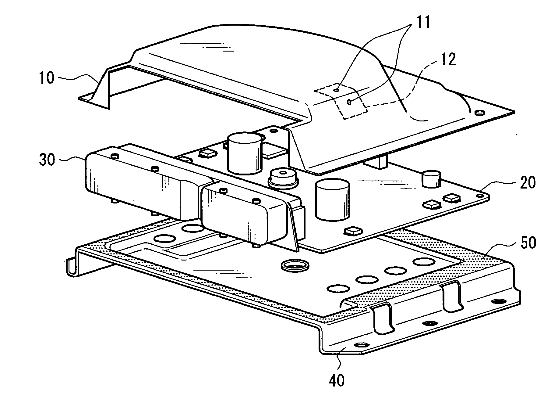
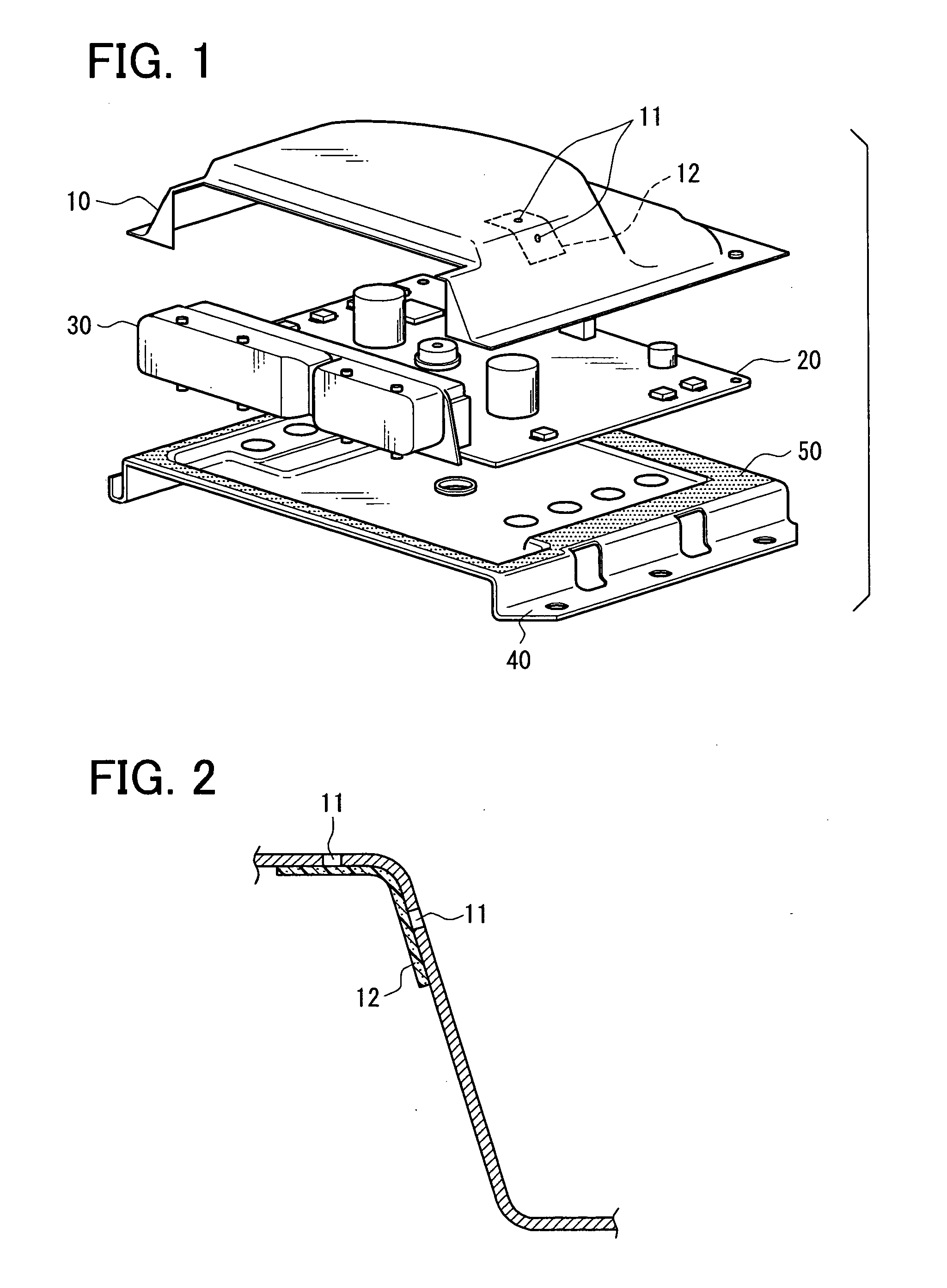
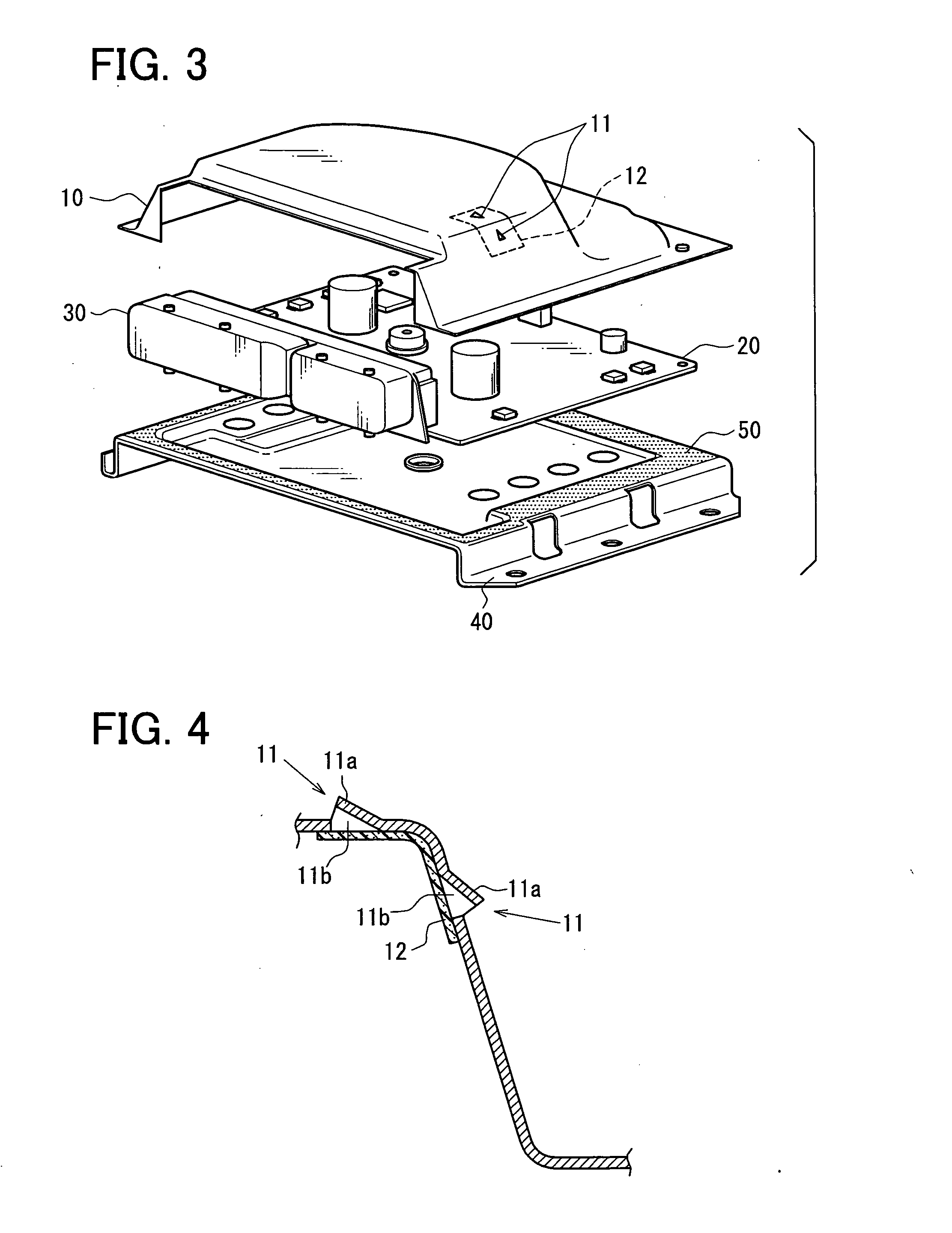
[0040] Next, an example 1 of the waterproof case will be described with reference to FIG. 3 and FIG. 4.

[0041] In the example 1, as shown in FIG. 3 and FIG. 4, the opening 11a of the breathing hole 11 is formed at the bottom surface of a triangular pyramid projecting to the outside of the cover member 10. In this manner, by forming the opening 11a of the breathing hole 11 at the bottom surface of a triangular pyramid projecting to the outside of the cover member 10, it is possible to reduce a possibility that the opening 11a is covered with water from a part other than the bottom surface of the triangular pyramid. That is, the portion other than the bottom surface of the triangular pyramid acts as the cover of the opening 11a. This can reduce a possibility that the opening 11a will be covered with water.

[0042] The waterproof case is different in a direction in which it is easily covered with water depending on use. Hence, by packaging the waterproof case on a body to be packaged in...

example 2

[0044] Next, an example 2 of the waterproof case will be described with reference to FIG. 5 and FIGS. 6A and 6B.

[0045] In the example, 2, as shown in FIG. 5 and FIGS. 6A and 6B, openings 11c of the breathing holes 11 are formed at an outside of a circular projecting groove 13 projecting outside the cover member 10. In this manner, by forming the openings 11c of the breathing holes 11 outside of the circular projecting groove 13 projecting outside the cover member 10, even when the waterproof case is covered with water, the water easily flows along the circular projecting groove 13, which hence can reduce a possibility that the breathing holes 11 will be closed by the water.

[0046] Further, as shown in FIG. 5 and FIGS. 6A and 6B, by forming the openings 11c of the breathing holes 11 in four outside directions of the circular projecting groove 13, it is possible to further reduce a possibility that the breathing holes 11 will be closed by water. That is, even when the openings 11c in...


PUM


Abstract

A waterproof case for housing an electronic component includes a case member that has a plurality of breathing holes, and a breathable waterproof filter fitted to the case member at a position corresponding to the breathing holes to cover the breathing holes. For example, open surfaces of at least two of the breathing holes, opened outside of the case member, can be made to face in different directions. Furthermore, the breathing hole has an open area on a side of the breathable waterproof filter, which is larger than an open area of the breathing hole on a side opposite to the breathable waterproof filter, in the case member. Accordingly, the waterproof case enhances waterproofness while circulating air between the inside and the outside of the waterproof case.

Description

CROSS REFERENCE TO RELATED APPLICATION [0001] This application is based on Japanese Patent Application No. 2005-360779 filed on Dec. 14, 2005, the contents of which are incorporated herein by reference in its entirety. FIELD OF THE INVENTION [0002] The present invention relates to a waterproof case with a waterproof structure, for housing an electronic component. BACKGROUND OF THE INVENTION [0003] In a waterproof case with a waterproof structure disclosed in JP-A-11-111381, a cover is provided with a filter fitting part. This filter fitting part is provided with a filter breathing hole, a filter welding surface to which a filter is welded and which is formed so as to surround the periphery of this filter breathing hole, and a projection for forming the filter fixing part. A water-repellent filter is placed on the filter welding surface and is rounded inside while the projection is melted to form the filer fixing part, thereby being fixed. [0004] As described above, by providing the ...

Claims


Application Information

Patent Timeline
Patent Type & Authority Applications(United States)
IPC IPC(8): H01R13/40
CPCH05K5/0047H05K5/0213H05K5/068H05K5/0215
Inventor SHINODA, TAKUYAKAMIYA, TAKAMICHIKATO, KEIICHI
Owner DENSO CORP
Why Eureka
Try Eureka