Providing detailed information on powered device in system for supplying power over communication link

Inactive Publication Date: 2007-06-14
ANALOG DEVICES INT UNLTD
View PDF10 Cites 80 Cited by
  • Summary
  • Abstract
  • Description
  • Claims
  • Application Information

AI Technical Summary

Problems solved by technology

Power supply cost in a PoE system can be significant.
However, if the system contains PDs that normally run at a low power level but have transient high power usage, this causes a conflict between the two requirements.
For example, if the power supply is sized to run near it's maximum capacity and multiple PDs consume maximum power, the system may be overloaded.
Currently, information on a

Method used


Image

  • Providing detailed information on powered device in system for supplying power over communication link
  • Providing detailed information on powered device in system for supplying power over communication link
  • Providing detailed information on powered device in system for supplying power over communication link

Examples


Embodiment Construction

[0026] The present disclosure will be made using the example of providing PD information to a PSE in a PoE system. It will become apparent, however, that the concepts described herein are applicable to any system for providing power over a communication link.

[0027] For example, a system of the present disclosure may be used in a local area network (LAN) having a plurality of nodes, a network hub and communication cabling connecting the nodes to the network hub for providing data communications. The network hub may have a power supply device for providing power to a PD over the communication cabling. The LAN may include a system for providing detailed PD information to the power supply device.

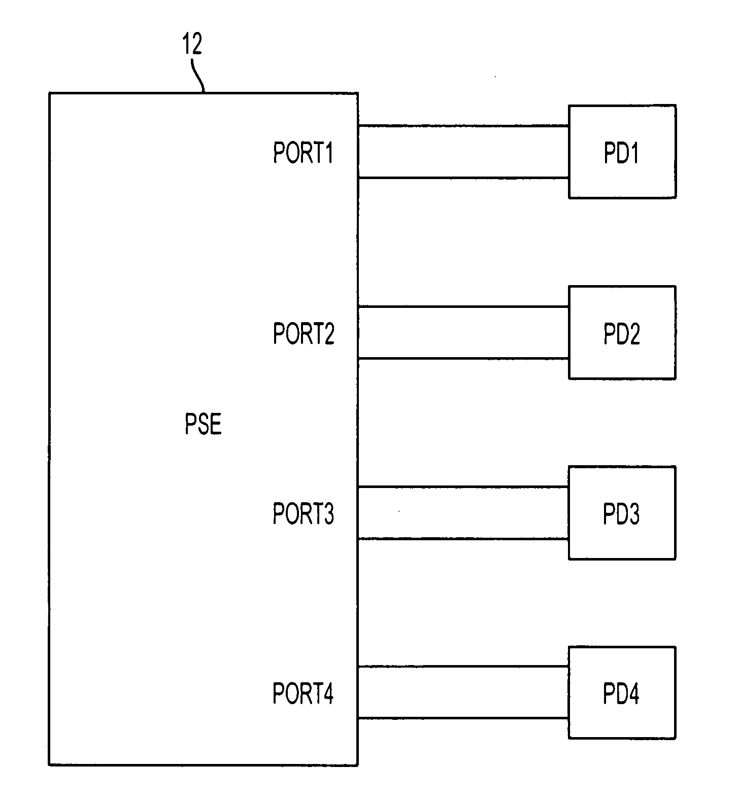
[0028]FIG. 1 shows a simplified block-diagram illustrating a PoE system 10 including a PSE 12 having multiple ports 1 to 4 connectable to Powered Devices (PD1 to PD4) via respective links, each of which may be provided using 2 or 4 sets of twisted pairs within an Ethernet cable. Although FIG. ...


PUM


Abstract

A powered device (PD) configured for receiving power over a communication link, such as an Ethernet link, has a power interface controller for implementing a power supply protocol. The power interface controller acquires multiple pieces of PD information representing multiple characteristics of the PD for transferring the PD information to a power supply device.

Description

[0001] This application claims priority of and incorporates by reference provisional U.S. patent application No. 60 / 749,048 filed on Dec. 12, 2005, and entitled “SYSTEM AND METHOD FOR SUPPORTING ADVANCED POWER OVER ETHERNET SYSTEM.”TECHNICAL FIELD [0002] This disclosure relates to power supply systems, and more particularly, to circuitry and methodology for providing information relating to a powered device coupled to a communication link, such as an Ethernet link. BACKGROUND ART [0003] Over the years, Ethernet has become the most commonly used method for local area networking. The IEEE 802.3 group, the originator of the Ethernet standard, has developed an extension to the standard, known as IEEE 802.3af, that defines supplying power over Ethernet cabling. The IEEE 802.3af standard defines a Power over Ethernet (PoE) system that involves delivering power over unshielded twisted-pair wiring from a Power Sourcing Equipment (PSE) to a Powered Device (PD) located at opposite sides of a ...

Claims


Application Information

Patent Timeline
IPC IPC(8): H04M9/00G05D11/00G06F1/00H04L12/28G05B11/01
CPCH04L12/10H04L25/0264H04L41/08H04L49/40Y02B60/43Y02B60/44Y04S40/162Y02D30/00Y04S40/00
Inventor STANFORD, CLAYTON REYNOLDS
Owner ANALOG DEVICES INT UNLTD
Why Eureka
Try Eureka