
Joint replacement prosthesis, joint replacement mounting stud and method

Inactive Publication Date: 2007-06-14
VERHOOGEN ALEX R
View PDF13 Cites 30 Cited by
  • Summary
  • Abstract
  • Description
  • Claims
  • Application Information

AI Technical Summary

Problems solved by technology

These stems have little fixation value, meaning they really do not offer significant strength to the attachment of the prosthesis to the bone.
However, these stems do significantly compromise the ability to remove such prostheses, thus complicating the process of revision surgery.
When inserting a knee prosthesis, the insertion of a tibial component causes the most soft tissue damage.

Method used


Image

  • Joint replacement prosthesis, joint replacement mounting stud and method
  • Joint replacement prosthesis, joint replacement mounting stud and method
  • Joint replacement prosthesis, joint replacement mounting stud and method

Examples


Embodiment Construction

[0046] This disclosure of the invention is submitted in furtherance of the constitutional purposes of the U.S. patent Laws “to promote the progress of science and useful arts” (Article 1, Section 8).

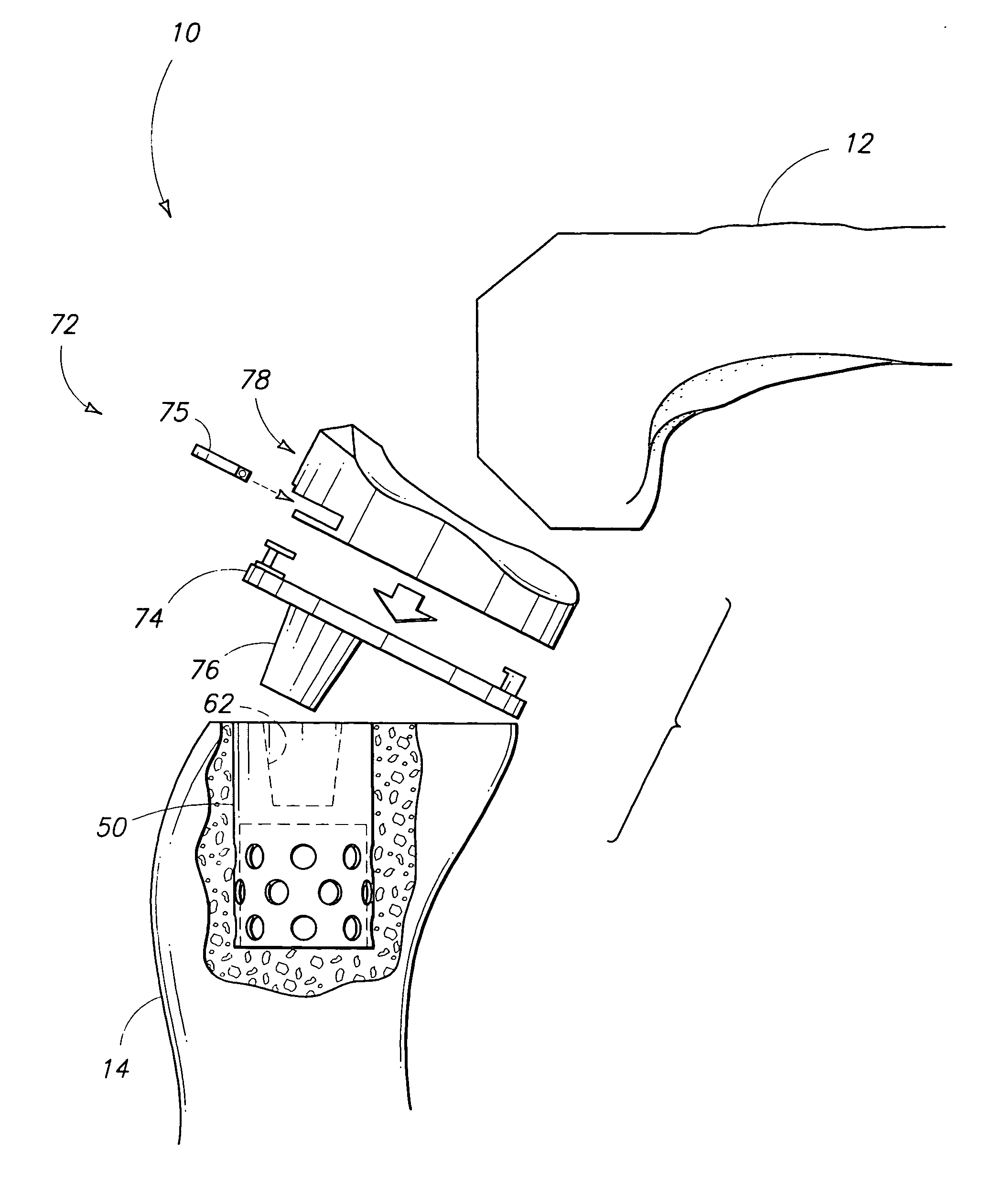
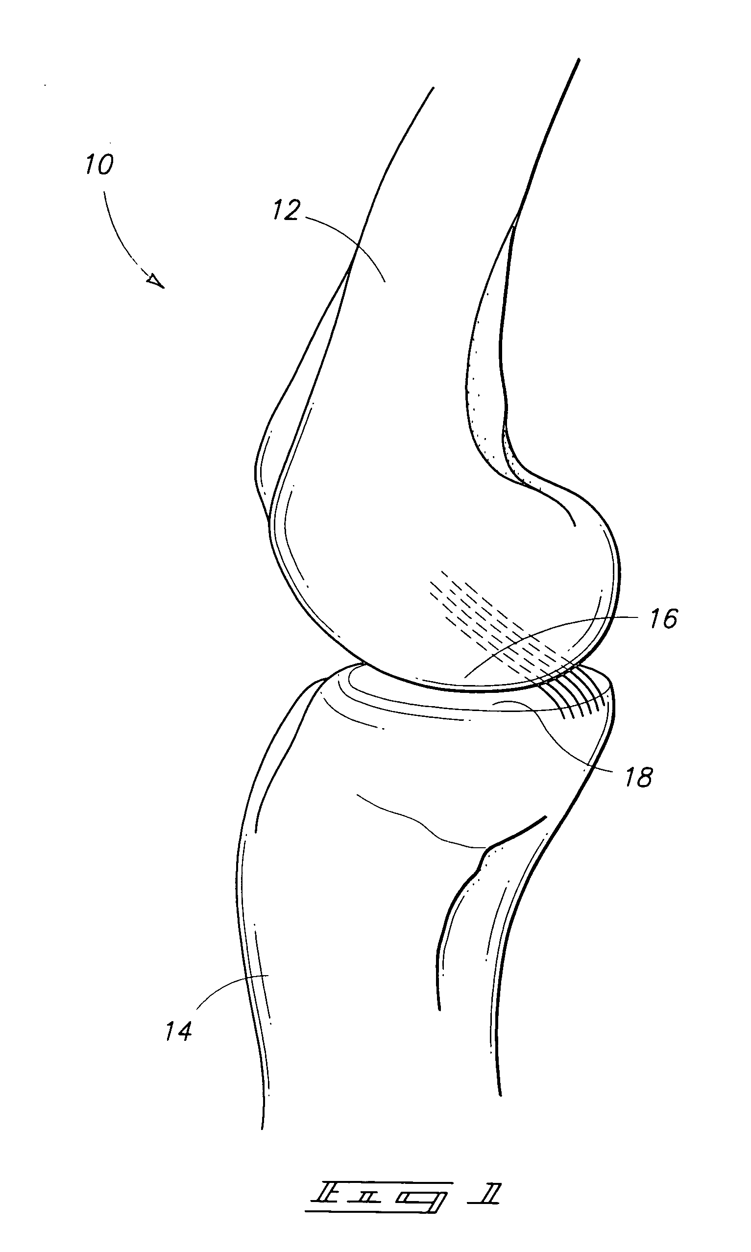
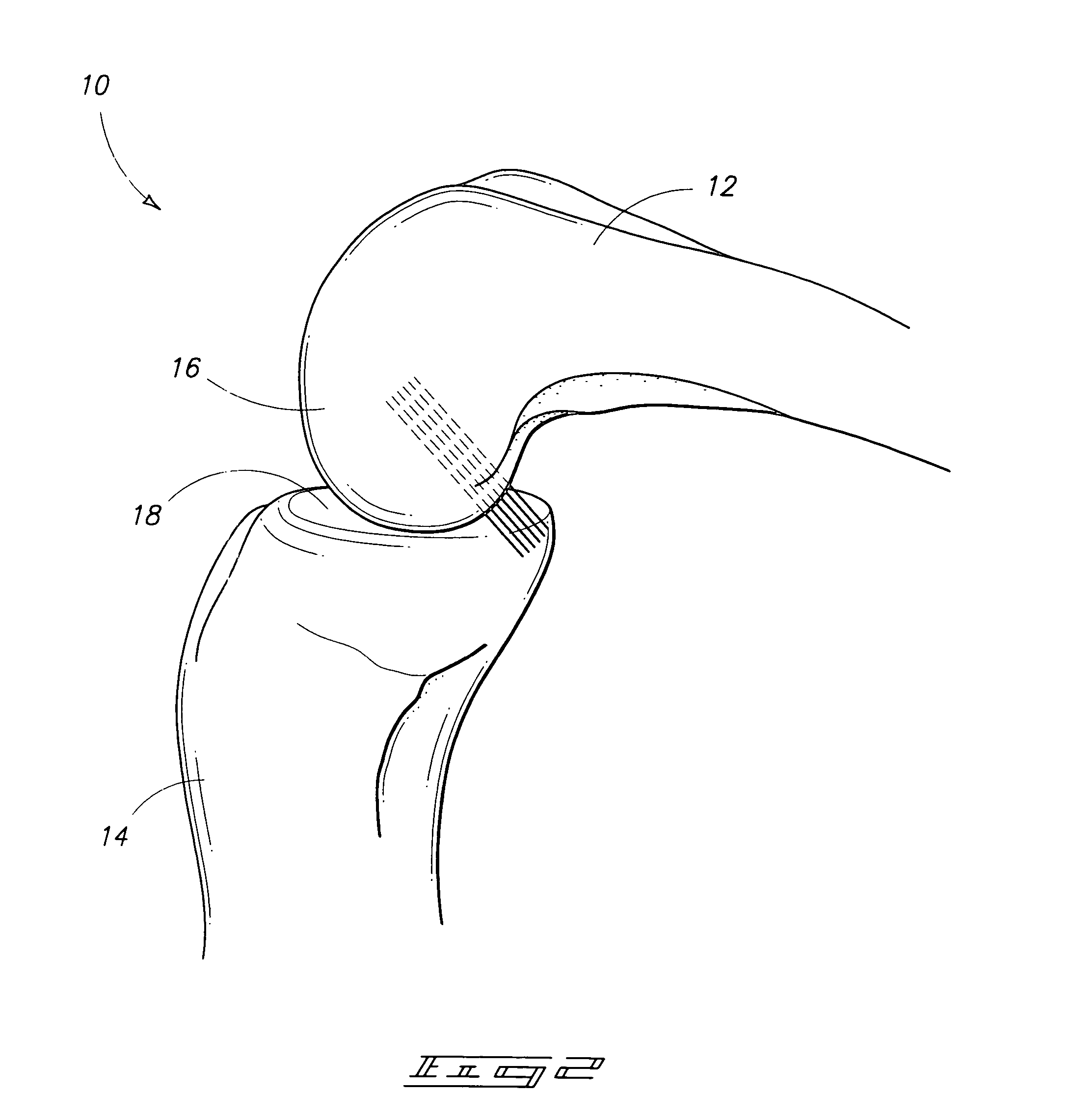
[0047] Reference will now be made to preferred embodiments of Applicant's invention. Exemplary implementations are described below and depicted with reference to the drawings comprising joint interface components and mounting studs for joint interface components of joint prostheses.

[0048] While the invention is described by way of preferred embodiments, it is understood that the description is not intended to limit the invention to these embodiments, but is intended to cover alternatives, equivalents, and modifications which may be broader than the embodiments, such as is defined within the scope of the appended claims.

[0049] In an effort to prevent obscuring the invention at hand, only details germane to implementing the invention will be described in great detail, with presently und...


PUM


Abstract

A prosthesis anchor component is provided. The prosthesis anchor component has a mounting stud having an elongated body with a tubular distal end and a proximal end. The tubular distal end includes a tubular wall portion with an open leading end and a plurality of apertures extending through the tubular wall portion. The proximal end has a mounting interface for securing a joint interface onto the stud. A method is also provided.

Description

RELATED PATENT DATA [0001] This application claims priority from U.S. Provisional Patent Application Ser. No. 60 / 750,846, which was filed Dec. 14, 2005, and which is incorporated by reference herein.TECHNICAL FIELD [0002] The present invention pertains to medical devices and methods. More particularly, the present invention relates to prosthetic joint components and anchors for prosthetic joint components, and methods. BACKGROUND OF THE INVENTION [0003] Joint arthroplasty involves the replacement of a natural joint with a prosthetic joint. Numerous joints can be replaced with prosthetic joints, including knee joints, hip joints and ankle joints. Such joints can be surgically replaced with a partial or complete prosthetic joint. For example, in the case of a knee joint a tibial component and a femoral component are installed onto a tibia and femur, respectively. In many cases, a tibial component has a tapered rectangular stem that is installed into a complementary receiving bore that...

Claims


Application Information

Patent Timeline
IPC IPC(8): A61F2/30
CPCA61B17/1637A61B17/1675A61B17/1764A61F2/30721A61F2/3603A61F2/38A61F2/3886A61F2002/30133A61F2002/30235A61F2002/30271A61F2002/30332A61F2002/30497A61F2002/30502A61F2002/30604A61F2002/30785A61F2002/30787A61F2002/30789A61F2002/30841A61F2002/30878A61F2002/30892A61F2220/0025A61F2220/0033A61F2230/0015A61F2230/0069A61F2230/0082A61B17/175A61B2017/1775A61B2017/1778A61F2002/30261A61F2002/30495A61F2002/305A61F2002/30593A61B17/1775A61B17/1778
Inventor VERHOOGEN, ALEX R.
Owner VERHOOGEN ALEX R
Learn More