Systems and methods for testing a wind turbine

a technology of wind turbine and system, applied in the field of wind turbines, can solve the problems of inconvenience, late delivery charge, inability to test the wind turbine in due time,

Active Publication Date: 2007-06-21
GENERAL ELECTRIC CO
View PDF17 Cites 12 Cited by
  • Summary
  • Abstract
  • Description
  • Claims
  • Application Information

AI Technical Summary

Problems solved by technology

However, if the POI substation is not constructed or not energized before a certain deadline, the wind turbine cannot be tested in due time and a late delivery charge is due to a customer

Method used


Image

  • Systems and methods for testing a wind turbine
  • Systems and methods for testing a wind turbine
  • Systems and methods for testing a wind turbine

Examples


Embodiment Construction

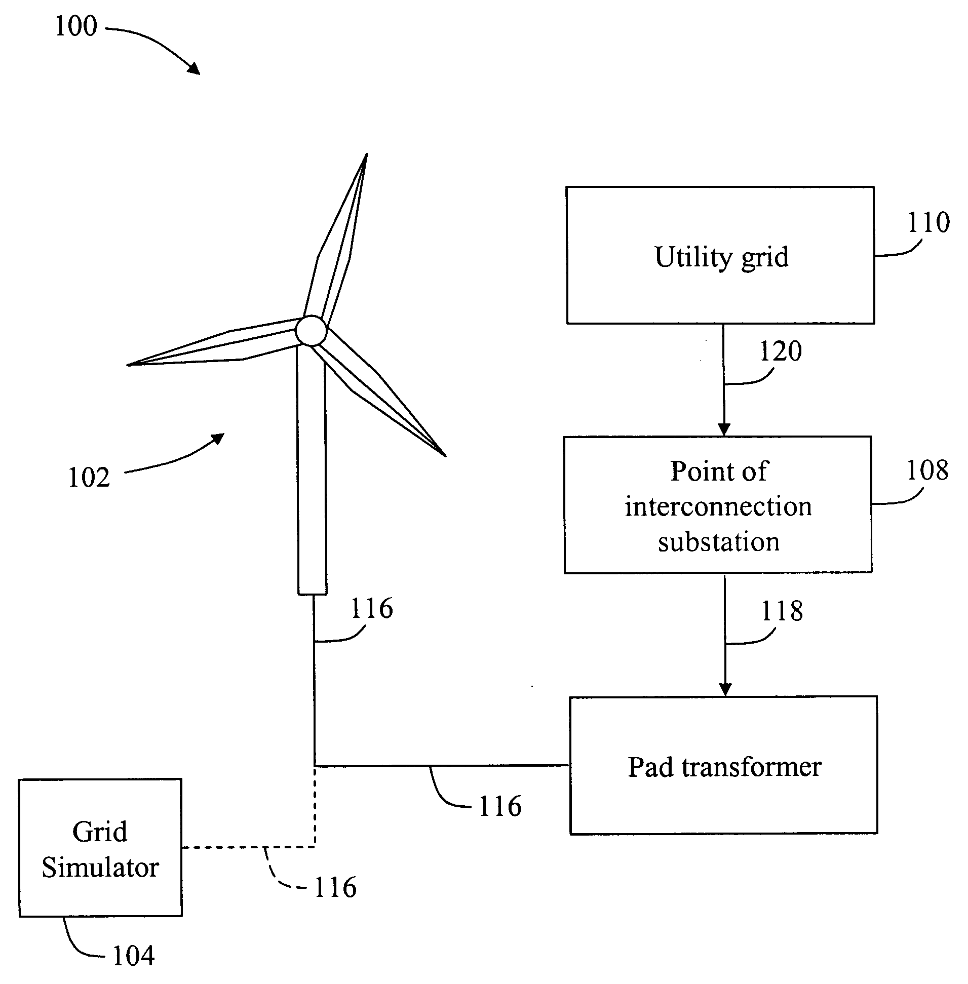
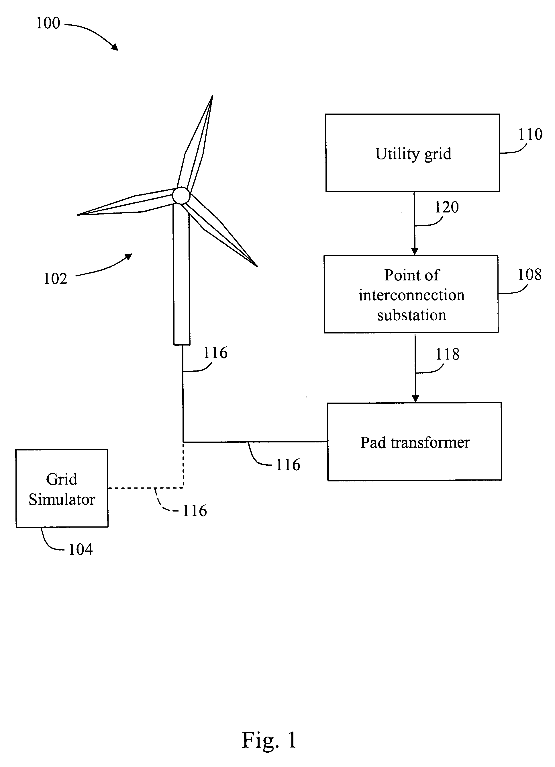
[0016]FIG. 1 is a block diagram of an embodiment of a system 100 for testing a wind turbine. System 100 includes a wind turbine 102, a grid simulator 104, a pad transformer 106, a point of interconnection (POI) substation 108, and a utility grid 110. Wind turbine 102 may output 1.5 megawatt (MW) of power, Alternatively, wind turbine 102 may output 2.3, 2.5, 2.7, or alternatively 3.6 MW of power. Pad transformer 106 can have a secondary winding at 575 volts alternating current (VAC) and a primary winding at 12 kilovolt alternating current (kVAC), and utilizes a power of 1.75 megavolt amperes (MVA). Alternatively, pad transformer 106 can have a primary winding at 34.5 kVAC and a secondary winding at 575 VAC, and utilizes a power of 1.75 MVA. Utility grid 110 may be a plurality of businesses or homes that utilize power from wind turbine 102. In an alternative embodiment, a plurality of wind turbines are coupled to utility grid 110 in a similar manner in which wind turbine 102 is couple...


PUM


Abstract

A system for testing is described. The system includes a wind turbine, a grid generator configured to generate power and coupled to the wind turbine, and a portable load coupled to the grid generator.

Description

BACKGROUND OF THE INVENTION [0001] This invention relates generally to wind turbines and more particularly to systems and methods for testing power production capability of a wind turbine. [0002] A wind turbine is tested by using a point of interaction (POI) substation before supplying the wind turbine to a customer. However, if the POI substation is not constructed or not energized before a certain deadline, the wind turbine cannot be tested in due time and a late delivery charge is due to a customer. Moreover, if the POI substation is constructed and energized close to a due date for delivering the wind turbine to the customer, a time crunch and therefore, an inconvenience is created. BRIEF DESCRIPTION OF THE INVENTION [0003] In one aspect, a system for testing is described. The system includes a wind turbine, a grid generator configured to generate power and coupled to the wind turbine, and a portable load coupled to the grid generator. [0004] In another aspect, a system for test...

Claims


Application Information

Patent Timeline
IPC IPC(8): F03D9/00H02P9/04G01M99/00
CPCG01R31/34Y02E10/72
Inventor HORNEMANN, MICHAEL ULFERTGALLOWAY, STEVEN
Owner GENERAL ELECTRIC CO
Why Eureka
Try Eureka